1. Introduction
This manual provides instructions for the safe and effective operation of the ALLOSUN EM420B Digital Multimeter. This compact 3 1/2 digit digital multimeter is designed for measuring DC and AC voltage, DC and AC current, resistance, temperature, diode, transistor, continuity, and capacitance. It features polarity indication, data hold, MAX mode, overrange indication, and automatic power-off. Please read this manual thoroughly before use.
2. Safety Information
WARNING:
- Always ensure the multimeter is set to the correct function and range before making measurements.
- Do not exceed the maximum input values for any range. Maximum operating voltage is 1000 Volts.
- Exercise extreme caution when working with live circuits.
- Inspect test leads for damage before each use. Do not use if insulation is compromised.
- Replace batteries immediately when the low battery indicator appears to ensure accurate readings.
- Do not operate the multimeter if it appears damaged or is not functioning properly.
- Refer to the manual for specific CAT rating information and appropriate usage environments.
3. Product Overview
The ALLOSUN EM420B Digital Multimeter is a versatile tool for electrical measurements. Below is an image illustrating its main components.

Figure 3.1: Front view of the ALLOSUN EM420B Digital Multimeter, showing the LCD display, rotary function switch, and input terminals.
3.1 Display
The multimeter features a 3 1/2 digit backlight LCD with a maximum reading of 1999. It updates 2-3 times per second.

Figure 3.2: Close-up of the LCD display, indicating measurement values and units.
3.2 Controls and Terminals
- Rotary Switch: Used to select measurement functions and ranges.
- FUNC Button: Selects between different functions within a single rotary switch position (e.g., AC/DC, Diode/Continuity).
- RANGE Button: Manually selects measurement range or toggles auto-ranging.
- MAX/H Button: Activates MAX mode (displays maximum reading) or Data Hold (freezes current reading). Press for 2 seconds for MAX mode.
- DATA H Button: Activates Data Hold function.
- Backlight Button: Activates the display backlight.
- INPUT Terminal: Positive input for most voltage, resistance, and capacitance measurements.
- COM Terminal: Common (negative) input for all measurements.
- 10A Terminal: Input for high current (up to 10A) measurements.
- mA/µA Terminal: Input for low current (mA/µA) measurements.
4. Setup
4.1 Battery Installation
The multimeter is powered by three 1.5V AAA batteries (not provided). To install or replace batteries:
- Ensure the multimeter is turned off and test leads are disconnected.
- Locate the battery compartment on the back of the unit.
- Use a screwdriver to open the battery compartment cover.
- Insert three AAA batteries, observing correct polarity (+ and -).
- Replace the battery compartment cover and secure it with the screw.

Figure 4.1: Rear view of the multimeter, highlighting the battery compartment.
A low battery indicator will appear on the display when batteries need replacement.
5. Operating Instructions
5.1 General Operation
- To turn on the multimeter, rotate the function switch from OFF to the desired measurement function.
- The multimeter features automatic power-off to conserve battery life. It will power off after a period of inactivity.
- To turn off, rotate the function switch to OFF.
5.2 Measuring DC Voltage (V=)
- Insert the red test lead into the "INPUT" jack and the black test lead into the "COM" jack.
- Set the rotary switch to the "V=" position.
- Connect the test leads across the component or circuit to be measured.
- Read the voltage value on the display. The polarity will be indicated.
5.3 Measuring AC Voltage (V~)
- Insert the red test lead into the "INPUT" jack and the black test lead into the "COM" jack.
- Set the rotary switch to the "V~" position.
- Connect the test leads across the AC voltage source.
- Read the voltage value on the display.
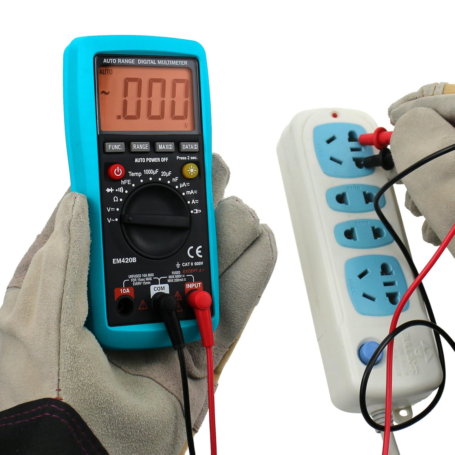
Figure 5.1: Measuring AC voltage from a power outlet.
5.4 Measuring DC Current (A=, mA=, µA=)
CAUTION: Never connect the multimeter in parallel with a voltage source when measuring current, as this can damage the meter or blow the fuse.
- Determine the expected current range. For currents up to 10A, use the "10A" jack. For lower currents, use the "mA/µA" jack. The black lead always goes into "COM".
- Set the rotary switch to the appropriate "A=", "mA=", or "µA=" position.
- Break the circuit and connect the multimeter in series with the load.
- Read the current value on the display.
5.5 Measuring AC Current (A~, mA~, µA~)
CAUTION: Never connect the multimeter in parallel with a voltage source when measuring current.
- Determine the expected current range. For currents up to 10A, use the "10A" jack. For lower currents, use the "mA/µA" jack. The black lead always goes into "COM".
- Set the rotary switch to the appropriate "A~", "mA~", or "µA~" position.
- Break the circuit and connect the multimeter in series with the load.
- Read the current value on the display.
5.6 Measuring Resistance (Ω)
- Insert the red test lead into the "INPUT" jack and the black test lead into the "COM" jack.
- Set the rotary switch to the "Ω" position.
- Ensure the circuit or component is de-energized before measuring resistance.
- Connect the test leads across the component.
- Read the resistance value on the display.
5.7 Diode Test
- Insert the red test lead into the "INPUT" jack and the black test lead into the "COM" jack.
- Set the rotary switch to the "Diode Test" position (indicated by a diode symbol).
- Connect the red lead to the anode and the black lead to the cathode of the diode.
- The display will show the forward voltage drop. Reverse the leads; the display should show "OL" (open loop) for a good diode.
5.8 Continuity Test
- Insert the red test lead into the "INPUT" jack and the black test lead into the "COM" jack.
- Set the rotary switch to the "Continuity Test" position (indicated by a continuity symbol).
- Connect the test leads across the circuit or component.
- If continuity exists (resistance below approximately 50Ω), the built-in buzzer will sound. The display will show the resistance value.
5.9 Transistor Test (hFE)
- Set the rotary switch to the "hFE" position.
- Insert the transistor (NPN or PNP) into the appropriate sockets of the hFE adapter.
- Read the hFE value on the display.

Figure 5.2: Performing a transistor hFE test using the adapter.
5.10 Capacitance Measurement
(Applicable to EM420B model only)
- Insert the red test lead into the "INPUT" jack and the black test lead into the "COM" jack.
- Set the rotary switch to the capacitance range (e.g., "1000µF", "20µF", "200nF").
- Ensure the capacitor is fully discharged before measurement.
- Connect the test leads across the capacitor terminals.
- Read the capacitance value on the display.
5.11 Data Hold Function
Press the "DATA H" button to freeze the current reading on the display. Press it again to release the hold and resume live readings.
5.12 MAX Mode
Press and hold the "MAX/H" button for 2 seconds to activate MAX mode. The multimeter will display the maximum value measured since the mode was activated. Press again to exit MAX mode.
6. Maintenance
6.1 Cleaning
Wipe the case with a damp cloth and mild detergent. Do not use abrasives or solvents. Ensure the multimeter is off and disconnected from all circuits before cleaning.
6.2 Battery Replacement
Refer to Section 4.1 for battery replacement instructions. Always replace all three AAA batteries at the same time with new ones.
6.3 Fuse Replacement
If the current measurement function stops working, the fuse may be blown. Fuse replacement should only be performed by qualified personnel. Refer to the specifications for the correct fuse type and rating.
7. Troubleshooting
| Problem | Possible Cause | Solution |
|---|---|---|
| No display or dim display | Dead or low batteries | Replace batteries (Section 4.1) |
| "OL" (Overload) displayed | Input exceeds selected range or meter's maximum capacity | Select a higher range or ensure input is within meter's limits. |
| Incorrect readings | Incorrect function/range selected; poor test lead connection; low battery | Verify settings, check connections, replace batteries. |
| Current measurement not working | Blown fuse | Replace fuse (refer to Section 6.3). |
8. Specifications
| Parameter | Value |
|---|---|
| Display | LCD, 1999 counts, updates 2-3 times/sec |
| Overrange Indication | "OL" shown on the display |
| Battery | 3 x 1.5V AAA or equivalent (Not provided) |
| Negative Polarity Indication | Negative sign "-" shown automatically |
| Low Battery Indication | Battery symbol shown on the display |
| Operating Temperature | 0℃ ~ 40℃, <75%RH |
| Storage Temperature | -10℃ ~ 50℃, <85%RH |
| Dimensions | 158 x 75 x 35 mm |
| Weight | About 200g |
| Maximum Operating Voltage | 1000 Volts |
| Accessories | Manual, Test leads, K-type Thermocouple, Adapter |
9. Warranty and Support
For warranty information or technical support, please refer to the documentation included with your purchase or contact ALLOSUN customer service. Keep your purchase receipt as proof of purchase.