1. Introduction
The NCE Switch-8 Mk2 is an advanced 8-way DCC accessory decoder designed for controlling various accessories on your model railway layout. This unit allows for the digital command control of up to eight individual accessories, such as turnouts (points), signals, or other animated features, integrating them seamlessly into your DCC system. It provides reliable and precise operation, enhancing the realism and functionality of your layout.
2. Product Overview
The Switch-8 Mk2 functions as an interface between your DCC command station and up to eight electrically controlled accessories. It interprets DCC commands to activate its internal relays, providing a robust and isolated switching mechanism. Its compact design and screw terminal connections facilitate easy integration into existing or new layouts. The decoder is engineered for automatic operation, responding to digital commands from your DCC system.
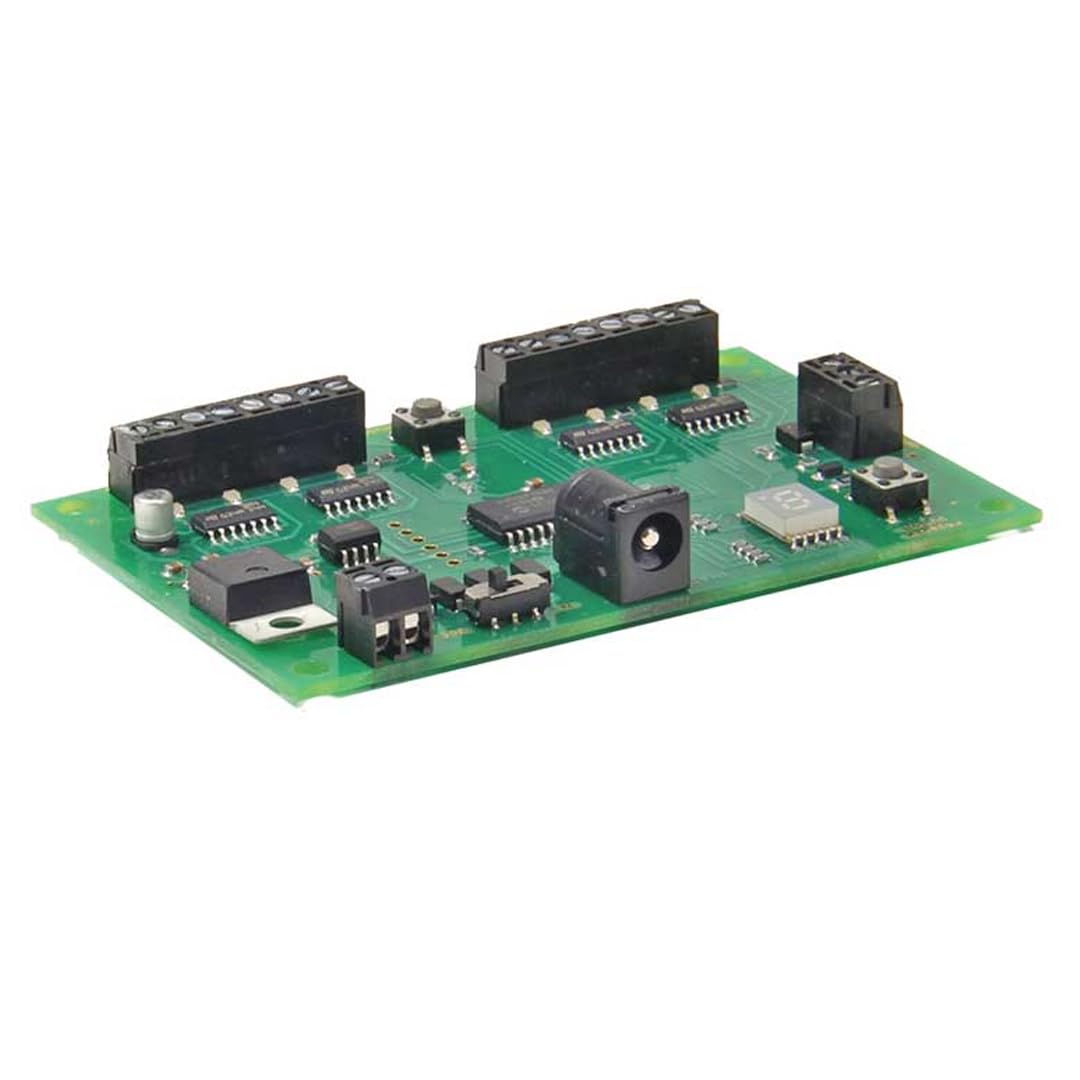
An image showing the NCE Switch-8 Mk2 DCC Accessory Decoder module, highlighting its screw terminals for connecting up to eight accessories and its compact design.
3. Safety Information
- Always disconnect power from your DCC system before installing or wiring the decoder.
- Ensure all wiring connections are secure to prevent short circuits and ensure proper operation.
- This device is intended for indoor use only in dry environments. Avoid exposure to moisture or extreme temperatures.
- Do not attempt to open or modify the decoder. There are no user-serviceable parts inside.
- Keep out of reach of children.
4. Package Contents
Verify that your package contains the following items:
- 1 x NCE Switch-8 Mk2 DCC Accessory Decoder
- 1 x Instruction Sheet (this manual)
5. Setup
5.1 Physical Installation
- Mounting: The Switch-8 Mk2 is designed for panel mounting. Choose a secure, dry location under your layout or within an accessory panel. Its dimensions are 8.5 x 4.5 x 0.56 inches.
- DCC Bus Connection: Connect the two input terminals of the Switch-8 Mk2 to your DCC track bus or a dedicated accessory bus. Ensure correct polarity if specified by your DCC system, though most accessory decoders are tolerant.
- Accessory Wiring: Connect your accessories (e.g., turnout motors, signals) to the eight sets of screw terminals on the decoder. Each set corresponds to one accessory output. Refer to your accessory's specific wiring instructions for proper connection to a relay switch. The Switch-8 Mk2 features Normally Open (NO) contacts for its relay type operation.
5.2 DCC Address Programming
Before operation, each output of the Switch-8 Mk2 must be assigned a unique DCC accessory address. The exact programming procedure varies depending on your DCC command station. Generally, you will:
- Place your DCC system into accessory programming mode.
- Select the desired accessory address for the first output (e.g., address 1).
- Send a command to activate that address (e.g., 'throw' or 'close' for a turnout). The Switch-8 Mk2 should acknowledge the programming, often indicated by a relay click.
- Repeat this process for each of the eight outputs, assigning consecutive or desired unique addresses.
Consult your DCC command station manual for detailed instructions on programming accessory decoders.
6. Operating Instructions
Once the Switch-8 Mk2 is installed and programmed, you can control your accessories using your DCC command station.
- Activating Accessories: From your DCC command station, select the accessory address you wish to control.
- Sending Commands: Send the appropriate command (e.g., 'throw' or 'close' for a turnout, 'on' or 'off' for a light) to change the state of the accessory. The Switch-8 Mk2's relays will respond, activating or deactivating the connected accessory.
- Operation Mode: The decoder operates in an ON-NONE-ON mode, meaning it can switch between two states for each output. The 8 positions refer to the 8 independent control channels available.
7. Maintenance
The NCE Switch-8 Mk2 is designed for reliable, long-term operation with minimal maintenance.
- Cleaning: Periodically, gently clean the exterior of the decoder with a soft, dry cloth to remove dust. Do not use liquid cleaners or solvents.
- Inspection: Occasionally inspect the wiring connections to ensure they remain secure and free from corrosion.
- No User-Serviceable Parts: The internal components are not user-serviceable. Do not attempt to open the casing.
8. Troubleshooting
If you encounter issues with your Switch-8 Mk2, refer to the following troubleshooting guide:
| Problem | Possible Cause | Solution |
|---|---|---|
| Accessory not responding to commands. | Incorrect DCC address; loose wiring; no DCC power. | Verify DCC accessory address programming. Check all wiring connections to the DCC bus and the accessory. Ensure DCC track power is supplied to the decoder. |
| Intermittent accessory operation. | Loose or poor wiring connections; electrical interference. | Ensure all screw terminal connections are tight. Check for any frayed wires or potential short circuits. Ensure proper grounding of your layout. |
| Decoder not powering on (no relay clicks). | No DCC power to the decoder; faulty DCC bus connection. | Confirm DCC track power is active. Check the wiring from the DCC bus to the decoder's input terminals. |
| Only some accessories respond. | Incorrect programming for specific outputs; faulty accessory wiring. | Re-program the non-responding outputs. Check the wiring for the specific accessories that are not working. |
9. Specifications
| Feature | Specification |
|---|---|
| Model | Switch-8 Mk2 |
| Brand | NCE |
| Circuit Type | 8-way |
| Number of Positions | 8 |
| Switch Type | Relay |
| Operation Mode | ON-NONE-ON |
| Contact Type | Normally Open |
| Connector Type | Screw |
| Mounting Type | Panel Mount |
| Material | Copper |
| Item Dimensions (L x W x H) | 8.5 x 4.5 x 0.56 inches |
| Item Weight | 0.12 Pounds |
| International Protection Rating | IP54 |
| Specification Met | CE, ETL, REACH, RoHS, WEEE |
| UPC | 816757011004 |
| Part Number | NCE0151 |
10. Warranty and Support
For specific warranty information, please refer to the official NCE website or the documentation provided at the time of purchase. NCE products are typically covered by a manufacturer's warranty against defects in materials and workmanship.
For technical support, troubleshooting assistance beyond this manual, or warranty claims, please contact NCE customer service directly. Contact information can usually be found on the NCE official website (www.ncedcc.com).