1. Description and Operation
This section provides a detailed overview of the Ford backhoe attachment, including its main components and their functions. The backhoe consists of a mainframe, swing post, cylinders, boom, dipstick, hoses and tubing, valves, cushions, buckets, and various attaching hardware. Power for the backhoe is supplied by a hydraulic pump mounted on the tractor.
1.1. Backhoe Components Overview
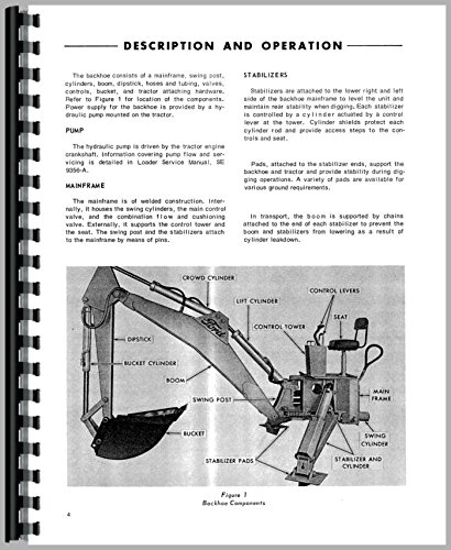
Figure 1: Diagram illustrating the main components of the backhoe, including the crowd cylinder, lift cylinder, control levers, seat, control tower, main frame, swing cylinder, stabilizer and cylinders, stabilizer pads, swing post, bucket, boom, dipstick, and bucket cylinder.
1.2. Stabilizers
Stabilizers are located on the lower right and left sides of the backhoe mainframe. Their purpose is to level the unit and maintain rear stability during digging operations. Each stabilizer is controlled by a cylinder, which also helps control the level at the tower. Cylinder shields protect the cylinder rods and provide access steps to the controls and seat.
Pads, attached to the stabilizer ends, support the backhoe and tractor, providing stability during digging. Various pad types are available to suit different ground conditions.
For transport, the boom is secured by chains attached to the end of each stabilizer. This prevents the boom and stabilizers from lowering due to cylinder rundown.
1.3. Pump
The hydraulic pump is driven by the tractor engine crankshaft. Detailed information regarding pump flow and servicing can be found in the Loader Service Manual, SE 9090-A.
1.4. Mainframe
The mainframe is constructed from welded components. Internally, it houses the swing cylinders, the main control valve, and the combination and cushioning valves. Externally, it supports the control tower and the seat. The swing post and stabilizers are attached to the mainframe using pins.
1.5. Other Components
- Swing Post, Swing Chain, and Linkage: Facilitate the rotational movement of the backhoe.
- Boom and Dipstick: The primary digging arms of the backhoe.
- Buckets: Various sizes and types available for different digging applications.
- Hoses and Tubing: Convey hydraulic fluid throughout the system.
- Cylinders: Hydraulic actuators for boom, dipstick, bucket, and stabilizer movements.
- Main Control Valve: Directs hydraulic fluid to various cylinders.
- Combination Valve: Integrates multiple hydraulic functions.
- Oil Flow: Describes the path and control of hydraulic fluid within the system.
2. Mechanical Adjustments
2.1. Cam Lever Swing Control Adjustment
This procedure details the steps required to properly adjust the cam lever for the swing control mechanism, ensuring smooth and accurate backhoe rotation.
3. Pressure Checks
Regular pressure checks are crucial for maintaining optimal hydraulic system performance and preventing component damage. This section outlines the procedures for various pressure tests.
- System Relief Valve Pressure Setting: Procedure for verifying and adjusting the main system relief pressure.
- Circuit Relief Valve Pressure Setting: Instructions for checking and setting individual circuit relief pressures.
- Backhoe Circuit Relief and Cushioning: Details on testing and adjusting relief and cushioning for backhoe circuits.
- Valve Test Equipment: Information on specialized tools required for hydraulic valve testing.
- Combination Valve Relief Valve Pressure Setting: Specific steps for the combination valve's relief pressure.
- Hydraulic Tests: General hydraulic system testing procedures.
- Hydraulic Pump Performance Test
- Circuit and Accumulated Leakage "Tee" Test
- Test Summary
- Cylinder Packing Leakage
- Pump Suction Leakage Test
4. Backhoe Overhaul
This section provides comprehensive instructions for disassembling, inspecting, repairing, and reassembling various components of the backhoe attachment.
- General Information: Safety precautions and general overhaul guidelines.
- Pump: Overhaul procedures for the hydraulic pump.
- Hoses and Tubing: Inspection, replacement, and routing guidelines.
- Cylinders: Disassembly, seal replacement, and reassembly of hydraulic cylinders.
- Bucket: Inspection and repair of bucket components.
- Dipstick: Maintenance and repair of the dipstick assembly.
- Boom: Inspection and repair of the boom structure.
- Swing Post: Overhaul of the swing post mechanism.
- Mainframe: Inspection and repair of the mainframe structure.
- Main Control Valve: Disassembly, cleaning, and reassembly of the main control valve.
- Combination Valve: Overhaul procedures for the combination valve.
5. Lubrication and Maintenance
Proper lubrication and routine maintenance are essential for the longevity and reliable operation of your backhoe attachment. This section details recommended practices.
- Hydraulic Oil: Specifications, checking levels, and replacement intervals.
- Oil Filter: Replacement procedures and recommended filter types.
- Service Schedule: A comprehensive schedule for all routine maintenance tasks.
6. Troubleshooting
This section provides guidance for identifying and resolving common operational issues with the backhoe attachment. It includes symptoms, possible causes, and recommended corrective actions.
Refer to the detailed troubleshooting charts within the manual for specific diagnostic steps related to hydraulic system malfunctions, mechanical failures, and operational difficulties.
7. Specifications
This section provides detailed technical specifications for the Ford backhoe attachment, including dimensions, capacities, and performance data.
- Backhoe General: General characteristics and features.
- Backhoe Dimensional Specifications - By Model: Detailed measurements specific to models 750, 753, and 755.
- Hydraulic System: Specifications for pump flow, pressure, and reservoir capacity.
- Cylinders - General: General specifications for hydraulic cylinders.
- Cylinders Dimensions - By Model: Specific cylinder dimensions for each model.
- Hydraulic Lines: Specifications for hydraulic hoses and tubing.
- Buckets - By Model: Available bucket sizes and types for each model.
- Optional Stabilizer Pads: Details on various stabilizer pad options.
- Special Tests: Information on any specialized testing procedures.
- Conversions for Specifications in Text: Units of measure and conversion factors used within the manual.