Introduction
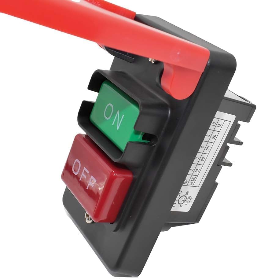
The Superior Electric SW56 is a robust push-button switch designed for use with table saws and other power tools. It features a large, easily accessible emergency stop cover for enhanced safety. This switch is a common replacement part for power tools, managing on/off functions and, in some applications, variable speed and electric braking. Due to mechanical wear over time, switches may require replacement to ensure proper tool operation.
This manual provides detailed instructions for the safe installation, operation, and maintenance of your SW56 switch.
Safety Information
WARNING: Always disconnect power to the tool before installing, servicing, or performing any maintenance on the switch. Failure to do so can result in serious injury or death.
- Ensure all wiring is performed by a qualified electrician or a person with thorough knowledge of electrical systems and local codes.
- This switch is intended to be connected to stranded wire with insulated crimp-type ring wire terminals.
- All crimps must be "pull-checked" to ensure that wires are securely crimped and will not fall out with moderate tension or when exposed to normal machine vibration.
- Verify the voltage and amperage ratings of your tool match the switch specifications before installation.
- Do not operate the switch if it is damaged or malfunctioning.

Setup and Installation
The SW56 switch is designed for snap-in mounting. It typically fits into a standard electrical gang box, though some installations may require a deep box or custom enclosure due to the switch's size and wiring requirements.
- Prepare the Mounting Location: Identify a suitable and secure location for the switch, preferably within easy reach during tool operation. Ensure the chosen electrical box (not included) provides adequate space for the switch and all wiring connections.
- Disconnect Power: Before beginning any wiring, ensure the power supply to the tool or circuit is completely disconnected at the main breaker.
- Wire the Switch: Refer to the wiring diagram (Figure 1) and the specifications for proper connections.
- Connect the incoming power (Line) to the appropriate terminals on the switch.
- Connect the outgoing power (Load) to the tool's motor or power input.
- Ensure all ground wires are properly connected to the switch and the electrical box, if applicable.
- Use insulated crimp-type ring wire terminals for secure connections. Perform a "pull-check" on each crimp to confirm its integrity.
- Mount the Switch: Once wired, carefully position the switch into the gang box opening. The snap-in design should secure it in place. Secure the switch plate to the box using appropriate screws.
- Test Functionality: Restore power to the circuit. Press the green "ON" button to start the tool and the large red "STOP" paddle to turn it off. Verify that the tool responds correctly to both actions.


Operating Instructions
The SW56 switch provides simple and intuitive control for your power tool.
- To Turn ON: Press the green "ON" button. The tool should start immediately.
- To Turn OFF (Normal Stop): Press the red "OFF" button. The tool will cease operation.
- To Turn OFF (Emergency Stop): Strike the large red "STOP" paddle. This provides a quick and easy way to shut down the tool in an emergency, even with a knee or hip.

Maintenance
The Superior Electric SW56 switch is designed for durability and requires minimal maintenance. However, regular inspection is recommended to ensure continued safe and reliable operation.
- Periodic Inspection: Regularly check the switch for any signs of physical damage, such as cracks in the housing, loose buttons, or frayed wires.
- Connection Check: Periodically verify that all electrical connections are secure and free from corrosion. Ensure crimped terminals remain tight.
- Cleaning: Keep the switch free from dust, sawdust, and debris. Use a dry, soft cloth for cleaning. Do not use liquid cleaners or solvents.
- Functionality Test: Before each use of the tool, briefly test the "ON" and "STOP" functions to ensure they operate smoothly and reliably.
Do not attempt to disassemble the switch. There are no user-serviceable parts inside.
Troubleshooting
If you experience issues with your SW56 switch, consider the following common problems and solutions:
| Problem | Possible Cause | Solution |
|---|---|---|
| Tool does not start when switch is pressed, or requires multiple attempts. | Failing or broken internal switch mechanism. Loose wiring connections. | Check all wiring connections for tightness. If connections are secure, the switch may need replacement. |
| Variable speed function or electric braking not working properly. | Internal switch malfunction related to these specific functions. | This indicates an internal failure of the switch. Replacement is necessary. |
| Switch feels loose or buttons are sticky. | Physical damage or accumulation of debris. | Inspect for physical damage. Clean the exterior of the switch. If the issue persists, replace the switch. |
| Switch does not fit standard gang box. | The switch dimensions require a deeper or specific type of electrical box. | Acquire a deeper electrical gang box or a suitable custom enclosure for installation. |
If troubleshooting steps do not resolve the issue, or if you suspect a serious electrical problem, discontinue use immediately and consult a qualified electrician.
Specifications
| Attribute | Detail |
|---|---|
| Manufacturer | Superior Electric |
| Model Number | SW56 |
| Part Number | SW56 |
| Voltage (Single Phase) | 120V / 230V |
| Amperage (120V) | 35 Amp |
| Horsepower (120V) | 2 HP |
| Amperage (230V) | 20 Amp |
| Horsepower (230V) | 3 HP |
| Wattage | 4600 watts |
| Item Weight | 3.2 ounces |
| Product Dimensions | 5 x 3.5 x 3.5 inches |
| Material | Polybutylene Terephthalate |
| Mounting Type | Snap In Mount |
| Switch Style | Pushbutton Switch |

Warranty and Support
For warranty information or technical support regarding your Superior Electric SW56 switch, please refer to the manufacturer's official website or contact their customer service department directly. Keep your purchase receipt as proof of purchase.
Visit the Superior Electric Store on Amazon for more products and information.