1. Introduction
This manual provides detailed instructions for the Q-BAIHE LJM L20SE 350W+350W 4ohm Amplifier Board. It covers product features, technical specifications, setup procedures, operational guidelines, maintenance tips, and troubleshooting information to ensure optimal performance and longevity of your amplifier board.
2. Product Overview
The LJM L20SE amplifier board is designed for high-fidelity audio applications, offering excellent control, low distortion, and wide voltage support. Each channel features two ON Semiconductor original power tubes (TTA1943/TTC5200) for high-power, high-current output, capable of handling a maximum load current of 20A. The design incorporates precision 1% copper-foot resistors and high-quality imported original capacitors from brands like NIPPON CHIEMI-CON, nichicon, or RUBYCON for superior performance.
Key Features:
- Dual AC power range of 12V to AC dual 45V.
- Recommended dual-voltage AC 36V for optimal performance.
- Low Total Harmonic Distortion (THD) of 0.009% at 1K Hz, 50W, 8R.
- High Slew Rate (SR) of 35V / US.
- Low Noise level of 92DBU.
- Equivalent Input Noise (EIN) of 114 DB.
- Wide Frequency Response of 20-20KHz ±0.5 DB.
- Voltage gain of 34 times.
- Double-sided FR4 PCB with 2MM thick plate and 75 UM thick copper wire.

Figure 1: Top-down view of two LJM L20SE amplifier boards, showcasing the layout of components including capacitors, resistors, and power transistors.

Figure 2: Angled view of two LJM L20SE amplifier boards, highlighting the three-dimensional arrangement of components and heat sinks.

Figure 3: Frontal view of two LJM L20SE amplifier boards, showing the input/output terminals and main power components.

Figure 4: Another angled perspective of the two LJM L20SE amplifier boards, emphasizing the connection points and overall build.

Figure 5: Exploded view of the LJM L20SE amplifier board components, including the main PCB and separate power transistors.
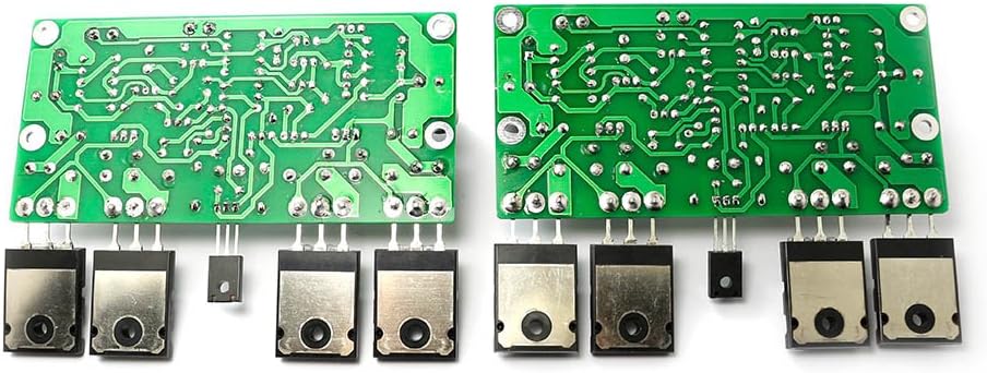
Figure 6: Bottom view of two LJM L20SE amplifier boards, revealing the solder points and circuit traces.
3. Specifications
| Parameter | Value |
|---|---|
| Model Number | LJM-FINAL-L20SE |
| Power Output | 200W (8Ω), 350W (4Ω) at DC ±65V |
| Total Harmonic Distortion (THD) | 0.009% (1K Hz, 50W, 8Ω) |
| Slew Rate (SR) | 35V / µS |
| Noise | 92DBU |
| Equivalent Input Noise (EIN) | 114 DB |
| Frequency Response | 20-20KHz ±0.5 DB |
| Voltage Gain | 34 times |
| Power Supply Range | Dual AC 12V to Dual AC 45V (Recommended: Dual AC 36V) |
| PCB Dimensions | 113 MM (width) x 71 MM (height) |
| Power Tubes per Channel | 2 x ON Semiconductor TTA1943/TTC5200 |
| Transistors | NJW0302G, NJW0281G, A1930, C5171 |
| Resistors | Precision 1% copper-foot resistors |
| Capacitors | Imported original (NIPPON CHIEMI-CON, nichicon, RUBYCON) |
| Item Weight | 1 pound |
4. Setup
Proper setup is crucial for the safe and optimal operation of your LJM L20SE amplifier board. Please follow the instructions carefully.
4.1 Power Supply Connection
The amplifier board requires a dual AC power supply within the range of 12V to 45V. A dual AC 36V power supply is recommended for best performance. Ensure the power supply is stable and capable of delivering the necessary current for your desired output power.
4.2 Wiring Diagram
Refer to the following diagram for correct wiring of the amplifier board, including connections for the power supply, signal input, potentiometer, speaker protection board, and speakers.
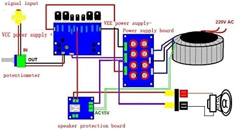
Figure 7: Wiring diagram for the LJM L20SE amplifier board, illustrating connections for power supply, signal input, potentiometer, speaker protection board, and speakers.
4.3 Component Integrity
It is critical to use the original transistors as specified for the L20SE amplifier. Do not substitute with other brands or models, as this may compromise performance or damage the board.
5. Operating Instructions
Once the amplifier board is correctly installed and wired, follow these steps for operation:
- Initial Check: Before applying power, double-check all connections to ensure they are secure and correctly polarized.
- Volume Control: Ensure any connected volume control (potentiometer) is set to its minimum position.
- Power On: Apply power to the amplifier board. Observe for any unusual sounds, smells, or visible issues.
- Signal Input: Connect your audio source to the signal input.
- Adjust Volume: Gradually increase the volume to your desired listening level.
- Power Off: When finished, reduce the volume to minimum before powering off the amplifier board.
6. Maintenance
To ensure the longevity and consistent performance of your amplifier board, adhere to the following maintenance guidelines:
- Cleanliness: Keep the amplifier board free from dust and debris. Use a soft, dry brush or compressed air for cleaning.
- Ventilation: Ensure adequate airflow around the board to prevent overheating. Do not obstruct any heat sinks or ventilation paths.
- Connection Checks: Periodically inspect all wiring connections for tightness and corrosion. Loose connections can lead to signal loss or damage.
- Environmental Conditions: Avoid exposing the board to moisture, extreme temperatures, or direct sunlight. Operate within a stable indoor environment.
- Component Inspection: Visually inspect capacitors for bulging or leakage, and resistors for discoloration, which may indicate component failure.
7. Troubleshooting
This section provides solutions to common issues you might encounter with your amplifier board.
7.1 No Sound Output
- Check Power: Verify that the power supply is connected correctly and providing the specified voltage.
- Input Signal: Ensure the audio source is active and the signal cables are properly connected to the amplifier's input.
- Speaker Connections: Confirm that speakers are correctly wired and functional. Check for any short circuits in the speaker cables.
- Volume Level: Make sure the volume control is not set to minimum.
7.2 Distorted Sound
- Input Signal Quality: Test with a different audio source to rule out issues with the source device or signal cables.
- Power Supply: An unstable or insufficient power supply can cause distortion. Verify the power supply voltage and current capabilities.
- Speaker Impedance: Ensure the connected speakers' impedance matches the amplifier's specifications (4-8 ohms).
- Overdriving: Reduce the input signal level or volume to prevent overdriving the amplifier.
7.3 Overheating
- Ventilation: Ensure the amplifier board has adequate ventilation and is not enclosed in a confined space.
- Heat Sinks: Verify that heat sinks are properly attached to the power transistors and are free from dust.
- Load Impedance: Operating the amplifier with a speaker load below the recommended impedance can cause excessive heat.
7.4 Humming Noise
- Grounding: Check all grounding connections. Improper grounding is a common cause of hum.
- Power Supply Filtering: Ensure the power supply has adequate filtering.
- Signal Cables: Use shielded audio cables and keep them away from power cables to minimize interference.
8. Warranty and Support
No specific warranty information is provided with this product data. For technical support, inquiries, or further assistance, please contact the manufacturer, Q-BAIHE, or your authorized point of purchase.