1. Introduction
This manual provides essential instructions for the safe and efficient operation, setup, and maintenance of your Holzmann ED 1000GDIG metal lathe. Please read this manual thoroughly before operating the machine to ensure proper use and to prevent injury or damage.
The Holzmann ED 1000GDIG is a versatile and durable lead and feed screw lathe, suitable for use in toolmaking, production, and training environments. It features an oversized spindle bore and an electromagnetic foot brake for enhanced safety and efficiency.
2. Safety Instructions
Always prioritize safety when operating machinery. Failure to follow safety guidelines can result in serious injury or damage to the equipment.
- Wear appropriate personal protective equipment (PPE), including safety glasses, hearing protection, and suitable clothing.
- Ensure the machine is properly grounded and connected to a 400V power supply.
- Keep the work area clean and well-lit. Remove any clutter that could cause tripping hazards.
- Never operate the machine under the influence of drugs or alcohol.
- Do not wear loose clothing, jewelry, or long hair that could get caught in moving parts.
- Always ensure the electromagnetic foot brake is functional and used for immediate spindle stops.
- Before making adjustments or maintenance, always turn off the machine and disconnect it from the power source.
- Use only recommended accessories and attachments.
- Keep hands clear of moving parts, especially the chuck and cutting tools.
3. Setup and Installation
Proper installation is crucial for the stability and performance of the lathe.
3.1 Unpacking and Placement
- Carefully unpack the machine and all accessories. Retain packaging for future transport if needed.
- Place the lathe on a stable, level surface capable of supporting its weight (Net weight: 630 kg).
- Ensure adequate clearance around the machine for safe operation and maintenance.
3.2 Electrical Connection
- Connect the machine to a 400V power supply. Ensure the electrical installation meets local regulations.
- Verify proper grounding to prevent electrical shock.
3.3 Initial Inspection
- Check all moving parts for freedom of movement.
- Ensure all bolts and fasteners are securely tightened.
- Lubricate all necessary points as indicated in the maintenance section.
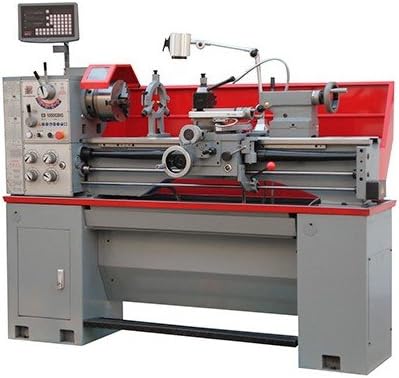
Figure 1: Overview of the Holzmann ED 1000GDIG Metal Lathe. This image shows the complete machine, highlighting its robust construction and various operational components, including the headstock, tailstock, carriage, and control panel.
4. Operating Instructions
This section details the basic operation of the Holzmann ED 1000GDIG lathe.
4.1 Power On/Off
- To power on, engage the main power switch.
- To power off, disengage the main power switch. In emergencies, use the electromagnetic foot brake for immediate spindle stop.
4.2 Spindle Speed Adjustment
The spindle speed can be adjusted quickly and easily via the gearbox. The available speed range is 70-1900 revolutions per minute (min-1).
- Refer to the speed chart on the machine for appropriate settings based on material and tool.
- Adjust the gear levers to select the desired speed range.
4.3 Chuck Operation
The lathe comes with a 3-jaw chuck (200 mm) and a 4-jaw faceplate (200 mm) with reversible jaws.
- Securely mount the workpiece in the chuck. Ensure it is centered and clamped tightly to prevent it from coming loose during operation.
- Use the chuck guard for safety.
4.4 Thread Cutting
The machine supports 32 metric thread pitches (0.45-10 mm) and 20 inch thread pitches (2.25-40 gg/1 inch).
- Consult the thread cutting chart on the machine for correct gear settings.
- Install the appropriate change gears from the provided set.
4.5 Tailstock Adjustment
The tailstock can be offset by +/- 5 mm for taper turning.
- Loosen the tailstock clamping bolts.
- Adjust the tailstock to the desired offset using the adjustment screw.
- Retighten the clamping bolts securely before operation.
5. Maintenance
Regular maintenance ensures the longevity and optimal performance of your lathe.
5.1 Cleaning
- After each use, clean chips and debris from the machine bed, carriage, and chuck.
- Use a brush or vacuum cleaner; never use compressed air as it can embed chips into moving parts.
5.2 Lubrication
- Regularly lubricate all sliding surfaces, lead screws, and gears with appropriate machine oil.
- Check the oil level in the gearbox and headstock, replenishing as needed.
5.3 Inspection
- Periodically inspect all belts, cables, and electrical connections for wear or damage.
- Check the condition of the chuck jaws and replace if worn.
- Ensure the electromagnetic foot brake is functioning correctly.
6. Troubleshooting
This section provides solutions to common operational issues.
| Problem | Possible Cause | Solution |
|---|---|---|
| Machine does not start | No power supply; Emergency stop engaged; Main switch off. | Check power connection (400V); Release emergency stop; Turn on main switch. |
| Excessive vibration | Unbalanced workpiece; Loose mounting; Worn bearings. | Re-balance workpiece; Tighten mounting bolts; Inspect and replace bearings if necessary. |
| Poor surface finish | Dull cutting tool; Incorrect speed/feed rate; Machine instability. | Sharpen or replace tool; Adjust speed and feed; Check machine leveling and mounting. |
| Spindle not stopping immediately | Electromagnetic foot brake malfunction. | Inspect and repair or replace the electromagnetic foot brake. Contact service if needed. |
7. Technical Specifications
| Feature | Specification |
|---|---|
| Motor Power S1 (W) | 1500 |
| Motor Power S6 (W) | 2100 |
| Voltage | 400 V |
| Bed Width | 187 mm |
| Bed Height | 305 mm |
| Distance Between Centers | 1000 mm |
| Max. Swing Over Bed | 360 mm |
| Max. Swing Over Cross Slide | 198 mm |
| Max. Swing Without Bridge | 470 mm |
| Spindle Speed Range | 70-1900 min-1 |
| Spindle Bore | 52 mm |
| Spindle Taper | MK6 (Camlock D1-5 according to DIN 55029) |
| Longitudinal Feed (16 settings) | 0.078-1.044 mm/rev |
| Longitudinal Slide Travel | 810 mm |
| Cross Slide Travel | 190 mm |
| Top Slide Travel | 88 mm |
| Tailstock Quill Travel | 100 mm |
| Metric Thread Pitches (32) | 0.45-10 mm |
| Inch Thread Pitches (20) | 2.25-40 gg/1 inch |
| Max. Cutting Tool Size | 20 x 20 mm |
| Net Weight | 630 kg |
| Gross Weight | 680 kg |
8. Warranty and Support
For warranty information, please refer to the documentation provided with your purchase or contact your authorized Holzmann dealer. For technical support, spare parts, or service inquiries, please contact Holzmann customer service or your local distributor.
Note: Software updates are unknown.