Introduction
This manual provides comprehensive instructions for the installation, operation, and maintenance of your SolarEpic EPEVER Tracer4215BN 40 Amp MPPT Solar Charge Controller. Please read this manual thoroughly before installation and use to ensure correct operation and to prevent damage to the controller or connected components. This controller is designed to efficiently manage power flow from your solar panels to your battery bank, optimizing charging performance.
Important Safety Instructions
Please observe the following safety precautions during installation and operation:
- Ensure all wiring is correctly polarized and securely connected to prevent short circuits and damage.
- Always disconnect the solar panel array and battery bank before performing any maintenance or adjustments to the controller.
- Wear appropriate personal protective equipment, including eye protection and insulated gloves, when working with electrical systems.
- Install the controller in a well-ventilated area, away from flammable materials and direct sunlight, to prevent overheating.
- Do not attempt to repair or modify the controller yourself. Refer to qualified service personnel for any repairs.
- Ensure the battery bank is properly ventilated to prevent accumulation of explosive gases.
- The controller is designed for specific battery types. Verify compatibility before connecting.
Product Overview
Key Features
- Negative Ground design with a maximum 150V PV input, allowing for series wiring of multiple solar panels.
- Advanced Maximum Power Point Tracking (MPPT) technology for optimal solar system efficiency, reaching up to 99.5%.
- Supports four charging options: Sealed, Gel, Flooded, and User-defined, compatible with AGM batteries.
- Comprehensive protection features: over temperature, over charging, PV and load short circuit, PV (battery) reversed polarity, and over current protection.
- Equipped with an RS-485 communication bus interface, utilizing the standard MODBUS protocol for external communication.
- Handles up to 600W of solar panel input for a 12V battery system, or 1200W for a 24V battery system.
Component Identification
The SolarEpic EPEVER Tracer4215BN controller features several key connection points and indicators:

Figure 1: Front view of the Tracer4215BN controller with terminals and indicators.
- PV Terminals: Connect to your solar panel array.
- Battery Terminals: Connect to your battery bank.
- Load Terminals: Connect to DC loads (e.g., lights, fans).
- Remote Temperature Sensor Port: For connecting an optional temperature sensor to optimize charging based on battery temperature.
- RS-485 Communication Port: For connecting to an MT-50 remote meter or PC software for monitoring and parameter settings.
- LED Indicators: Provide visual status of PV input, battery charge, and load output.
- Heat Sink: Large heat sink on the back and sides for efficient heat dissipation.
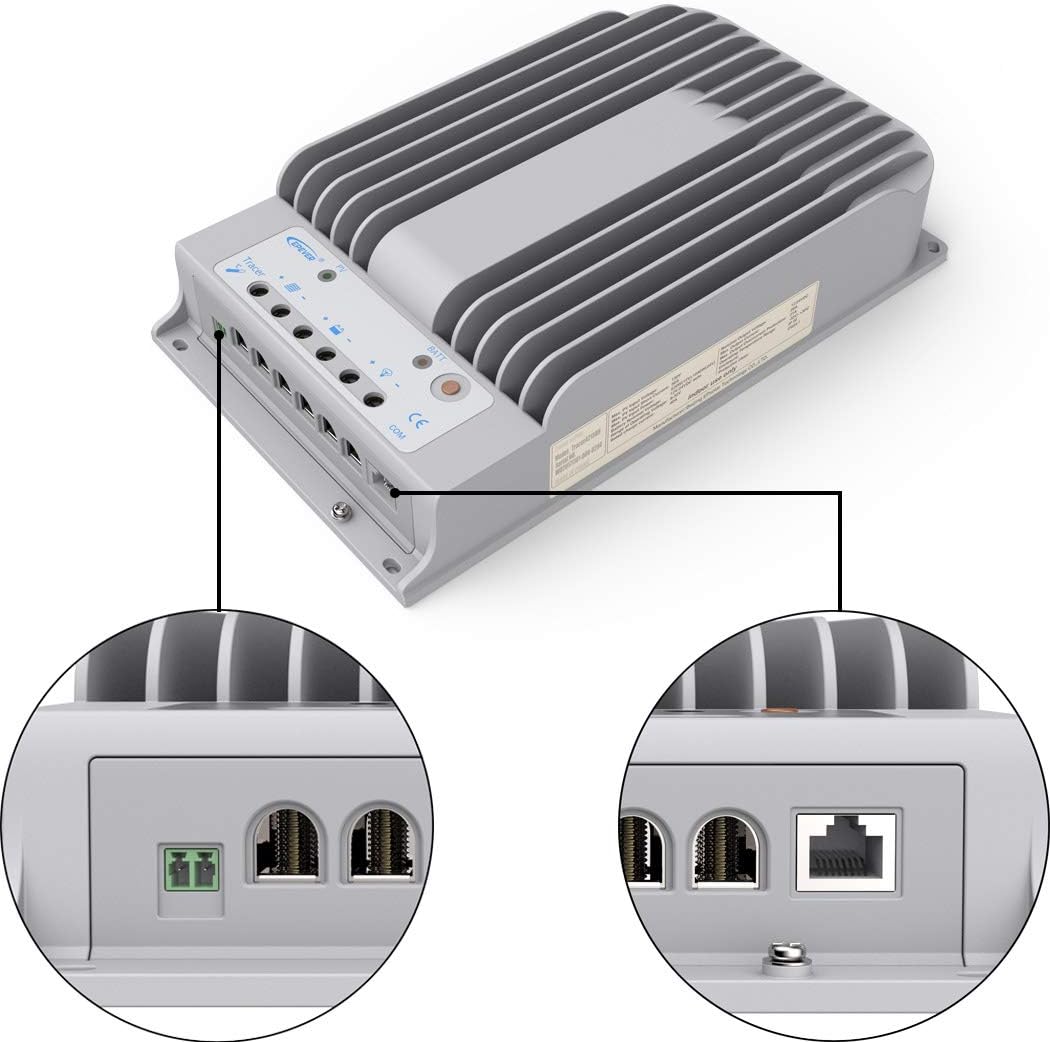
Figure 2: Detailed view of controller connection ports.
Technical Specifications
| Specification | Value |
|---|---|
| Model Number | Tracer4215BN |
| Nominal System Voltage | 12V / 24V Auto-recognition |
| Rated Charge Current | 40A |
| Rated Load Current | 20A |
| Max PV Open Circuit Voltage | 150V |
| Max PV Input Power (12V System) | 520W (Recommended 600W) |
| Max PV Input Power (24V System) | 1040W (Recommended 1200W) |
| Battery Type Compatibility | Sealed, Gel, Flooded, Lithium (LiFePO4) - requires MT50 remote meter for Lithium settings. |
| Grounding | Negative Ground |
| Communication | RS-485 (MODBUS protocol) |
| Dimensions | 11.91 x 2.5 x 7.19 inches |
| Weight | 6.38 pounds (2.9 kg) |
Installation Guide
Follow these steps for proper installation of your MPPT solar charge controller. Ensure all power sources are disconnected before beginning.
Wiring Sequence
- Connect the Battery: Always connect the battery to the controller first. Ensure correct polarity (positive to positive, negative to negative). The controller will automatically detect the system voltage (12V or 24V).
- Connect the Solar Panel: Connect the solar panel array to the PV terminals. Ensure correct polarity. The PV input voltage should not exceed 150V.
- Connect the DC Load (Optional): Connect your DC loads to the load terminals. Ensure correct polarity.
- Connect Remote Temperature Sensor (Optional): If using, connect the remote temperature sensor to its dedicated port and attach the sensor to the battery for accurate temperature compensation during charging.
- Connect Communication Cable (Optional): If using an MT-50 remote meter or PC software, connect the RS-485 communication cable.
Video: Installation guide for the SolarEpic MPPT Solar Charge Controller, demonstrating the connection sequence for battery, solar panel, and optional accessories. This video is provided by SolarEpic.
Wiring Precautions
- Ensure all connections are tight to avoid loose contacts and excessive heat.
- Use appropriate wire gauges for all connections to handle the expected current.
- Always connect the battery first and disconnect it last during installation or uninstallation.
Operation
Once installed, the controller will begin operating automatically. The LED indicators provide a quick status overview:
- PV LED: Indicates solar panel input status.
- Battery LED: Shows battery charging status.
- Load LED: Indicates DC load output status.
Battery Type Settings
The controller supports various battery types. To optimize charging, it is crucial to set the correct battery type. This typically requires an external device like the MT-50 remote meter or PC software.
- Connect the MT-50 remote meter or PC to the controller via the RS-485 port.
- Access the "Control Parameter" menu.
- Select your battery type: Sealed, Gel, Flooded, or User-defined.
- For custom settings or Lithium (LiFePO4) batteries, select "User-defined" and adjust parameters according to your battery manufacturer's specifications.
The controller comes with pre-programmed settings for Sealed, Gel, and Flooded batteries. For these types, only Equalize and Boost times can be changed. For other adjustments, the "User-defined" mode is necessary.
Load Control
The load output can be controlled manually or automatically based on various settings (e.g., dusk-to-dawn, timer). These settings are configurable via the MT-50 remote meter or PC software.
Maintenance
Regular maintenance ensures the longevity and optimal performance of your solar charge controller.
- Check Connections: Periodically inspect all wiring connections for tightness and corrosion. Tighten any loose connections.
- Clean the Controller: Keep the controller's heat sink and casing clean from dust and debris to ensure proper heat dissipation. Use a dry cloth for cleaning.
- Inspect Wiring: Check for any signs of wear, fraying, or damage to the cables. Replace damaged cables immediately.
- Monitor Performance: Regularly monitor the system's performance using the MT-50 remote meter or PC software to ensure stable operation and identify any anomalies.
- Battery Inspection: Follow the battery manufacturer's maintenance guidelines for your specific battery type.
Troubleshooting
If you encounter issues with your controller, refer to the following common problems and solutions:
| Problem | Possible Cause | Solution |
|---|---|---|
| No charging from PV | Solar panels not connected, incorrect polarity, insufficient sunlight, damaged panel/wiring. | Check PV connections and polarity. Ensure adequate sunlight. Inspect panels and wiring for damage. |
| Battery not charging | Battery not connected, incorrect polarity, battery voltage too low, incorrect battery type setting. | Verify battery connections and polarity. Check battery voltage. Ensure correct battery type is selected in settings. |
| Load not working | Load not connected, incorrect polarity, load overcurrent, battery voltage too low, load control settings. | Check load connections and polarity. Reduce load if overcurrent. Check battery voltage. Adjust load control settings. |
| Controller overheating | Poor ventilation, excessive current, high ambient temperature. | Ensure adequate airflow around the controller. Reduce load or PV input if consistently overheating. Relocate to a cooler area if possible. |
For more detailed troubleshooting or persistent issues, consult the full user manual provided with your product or contact customer support.
Warranty and Support
For information regarding product warranty, please refer to the warranty card included with your purchase or visit the official SolarEpic website. For technical support, product inquiries, or service, please contact SolarEpic customer service.
Brand: SolarEpic