1. Introduction
The Dr.Meter MS88 is an auto/manual ranging digital multimeter designed for accurate electrical measurements. Featuring a 4000-count LCD with backlight, it offers a wide range of functions including voltage, current, resistance, capacitance, frequency, duty cycle, diode test, continuity, and Non-Contact Voltage (NCV) detection. This manual provides essential information for safe and effective operation of your MS88 multimeter.
2. Safety Information
Always adhere to safety precautions when using the multimeter to prevent electric shock or personal injury. Incorrect use can lead to damage to the meter or the equipment under test.
- Do not exceed the maximum input values specified for each function.
- Ensure the test leads are in good condition and properly connected before making measurements.
- Do not use the meter if it appears damaged or if the battery cover is not properly closed.
- Exercise extreme caution when working with voltages above 30V AC RMS, 42V peak, or 60V DC. These voltages pose a shock hazard.
- Always disconnect power to the circuit and discharge all high-voltage capacitors before testing resistance, continuity, diodes, or capacitance.
- The Dr.Meter MS88 is rated for CAT IV 600V and CAT III 1000V. Understand these categories and use the meter appropriately.
- Replace the battery immediately when the low battery indicator appears.
3. Product Components and Features
Familiarize yourself with the various parts of your Dr.Meter MS88 Digital Multimeter.

Figure 3.1: Dr.Meter MS88 Multimeter Components. This image displays the Dr.Meter MS88 Digital Multimeter with its key components labeled, including the LCD display, function selection switch, input terminals, and control buttons. The red and black test leads are also shown connected to the positive and negative input ends.
- LCD Display: Shows measurement readings, units, and function indicators.
- Relative Measurement (REL) Button: Used to store the current reading as a reference for subsequent measurements.
- Auto/Manual Range Switch (RANGE) Key: Toggles between automatic and manual ranging modes.
- Function Switch (FUNC) Key: Selects sub-functions within a main rotary switch position (e.g., AC/DC voltage, diode/continuity).
- Function Selection Rotary Switch: Main control for selecting measurement types (e.g., V~, V-, A~, A-, Ω, NCV).
- Negative Input End (COM): Common terminal for all measurements, typically connected to the black test lead.
- Positive Input End (VΩHz, hFE μAmA, 20A): Terminals for connecting the red test lead based on the desired measurement.
- Data Hold (HOLD) Button: Locks the current reading on the display.
- Hz/Duty Measurement / Backlight Button: Selects frequency/duty cycle measurement or activates/deactivates the display backlight.
4. Setup
4.1 Battery Installation
The Dr.Meter MS88 is powered by batteries. Ensure batteries are correctly installed before use.
- Turn off the multimeter and disconnect all test leads.
- Locate the battery compartment on the back of the meter.
- Use a screwdriver to open the battery compartment cover.
- Insert new batteries, observing the correct polarity (+ and -).
- Securely close the battery compartment cover.

Figure 4.1: Dr.Meter MS88 Multimeter with Stand and Battery Access. This image shows the Dr.Meter MS88 Multimeter from the side and back, highlighting its integrated kickstand for hands-free use and the battery compartment, which requires a screwdriver to open for battery replacement.
4.2 Test Lead Connection
Connect the test leads to the appropriate input terminals for your desired measurement.
- Always connect the black test lead to the 'COM' (Common) terminal.
- For voltage, resistance, frequency, capacitance, diode, and continuity measurements, connect the red test lead to the 'VΩHz' terminal.
- For current measurements up to 400mA, connect the red test lead to the 'hFE μAmA' terminal.
- For high current measurements up to 20A, connect the red test lead to the '20A' terminal.
5. Operating Instructions
5.1 Power On/Off
Rotate the Function Selection Rotary Switch from 'OFF' to any desired measurement function to power on the meter. To power off, rotate the switch back to 'OFF'.
5.2 Function Selection
Turn the Function Selection Rotary Switch to the desired measurement category. Use the 'FUNC' button to cycle through sub-functions if available (e.g., AC/DC voltage, diode/continuity).
5.3 Auto/Manual Ranging
The meter defaults to auto-ranging. Press the 'RANGE' button to switch to manual ranging. In manual ranging, press 'RANGE' repeatedly to cycle through available ranges. Press and hold 'RANGE' to return to auto-ranging.
5.4 Data Hold
Press the 'HOLD' button to freeze the current reading on the display. Press it again to release the hold function and resume live measurements.
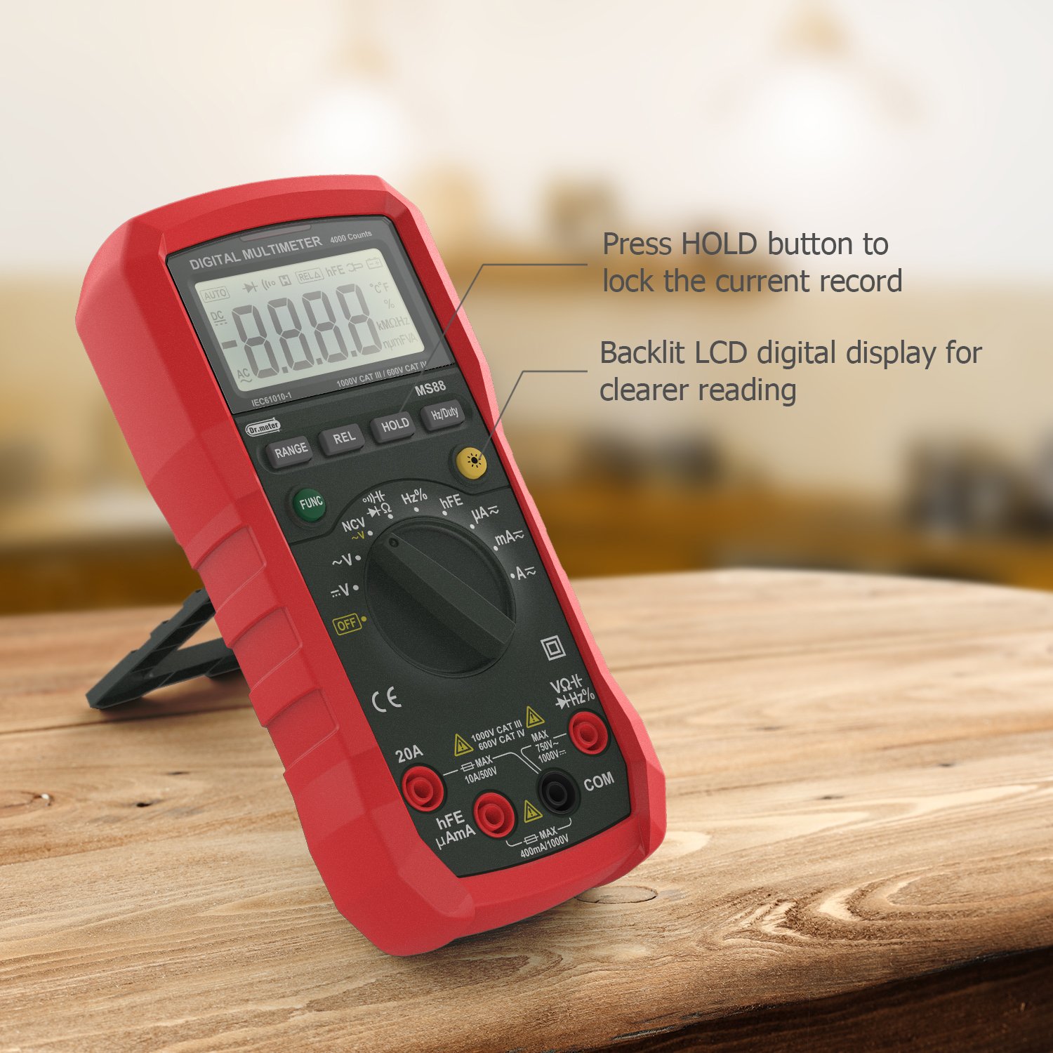
Figure 5.1: Data Hold and Backlight Features. This image illustrates the Dr.Meter MS88 Multimeter's display, showing how the 'HOLD' button can lock a measurement reading and indicating the backlit LCD for improved visibility in low-light conditions.
5.5 Backlight
Press the 'Hz/Duty' button briefly to turn the LCD backlight on or off. The backlight improves visibility in dimly lit environments.
5.6 Relative Measurement (REL)
Press the 'REL' button to enter relative measurement mode. The current display value becomes the reference, and subsequent measurements will show the difference from this reference. Press 'REL' again to exit this mode.
5.7 Non-Contact Voltage (NCV) Function
Rotate the Function Selection Rotary Switch to the 'NCV' position. Bring the top side of the multimeter near an AC voltage source. The meter will automatically flash and alarm when it detects AC voltage exceeding approximately 90V, indicating the presence of live voltage without direct contact.

Figure 5.2: NCV Function in Use. This image shows the Dr.Meter MS88 Multimeter detecting voltage near an electrical outlet using its Non-Contact Voltage (NCV) function, indicated by the display and the proximity to the power source.
5.8 Common Measurements
Below are examples of various measurement types.

Figure 5.3: Multifunctional Measurement Display. This image demonstrates the Dr.Meter MS88 Multimeter's capability to display multiple indicators, showing examples of voltage (V.F.C), frequency (Hz), and percentage (%) measurements on its LCD screen.
- Voltage (AC/DC): Rotate the switch to V~ (AC) or V- (DC). Connect leads in parallel to the circuit.
- Current (AC/DC): Rotate the switch to A~ (AC) or A- (DC). Connect leads in series with the circuit. Ensure correct terminal selection (μA/mA or 20A).
- Resistance (Ω): Rotate the switch to Ω. Connect leads across the component. Ensure power is off and capacitors are discharged.
- Continuity: Rotate the switch to the continuity/diode position and press 'FUNC' to select continuity. A buzzer will sound if resistance is below a certain threshold.
- Diode Test: Rotate the switch to the continuity/diode position and press 'FUNC' to select diode. Connect leads across the diode.
- Capacitance (F): Rotate the switch to the capacitance position. Connect leads across the capacitor. Ensure capacitor is discharged.
- Frequency/Duty Cycle (Hz/%): Rotate the switch to the Hz/% position. Connect leads to the signal source. Press 'Hz/Duty' to toggle between frequency and duty cycle.
- Transistor hFE: Rotate the switch to the hFE position. Insert the transistor leads into the appropriate sockets on the meter.

Figure 5.4: Multimeter in Application. This image shows the Dr.Meter MS88 Multimeter in use, with test leads connected to an electrical panel, demonstrating its practical application for electrical testing.
6. Maintenance
6.1 Cleaning
Wipe the meter with a damp cloth and mild detergent. Do not use abrasives or solvents. Keep the terminals free of dirt and moisture.
6.2 Battery Replacement
When the low battery indicator appears on the display, replace the batteries as described in Section 4.1. Always use the specified battery type.
6.3 Fuse Replacement
If the current measurement function fails, the fuse(s) may need replacement. Refer to the full service manual for fuse specifications and replacement procedures. Fuse replacement should only be performed by qualified personnel.
6.4 Storage
If the meter is not used for an extended period, remove the batteries to prevent leakage and damage. Store the meter in a cool, dry place away from direct sunlight.
7. Troubleshooting
If you encounter issues with your Dr.Meter MS88, refer to the following common troubleshooting steps:
- No Display/Meter Not Turning On: Check battery installation and ensure batteries are not depleted. Replace if necessary.
- Incorrect Readings: Verify test lead connections, ensure the correct function and range are selected, and check if the component under test is functioning correctly. For resistance measurements, ensure the circuit is de-energized.
- Continuity Buzzer is Quiet: This is a known characteristic for some units. Ensure the connection is solid and observe the display for continuity indication.
- Current Measurement Not Working: Check the fuse(s) inside the meter. If blown, replace with the correct type and rating.
- Display Shows 'OL' (Overload): The measured value exceeds the selected range. Switch to a higher range or ensure the meter is in auto-ranging mode.
For persistent issues, contact customer support.
8. Specifications
| Specification | Value |
|---|---|
| Model Number | MS88 |
| Display | 4000 Counts LCD with Backlight |
| Measurement Type | Multimeter |
| Power Source | Battery Powered |
| Safety Rating | CE, CAT IV 600V, CAT III 1000V |
| Item Weight | 454 g (1 Pound) |
| Package Dimensions | 20.83 x 12.95 x 5.84 cm |
| Color | Multicolour (Red) |
| Style | Digital |
9. Warranty and Support
Dr.Meter products are designed for reliability and performance. For warranty information or technical support, please refer to the documentation included with your purchase or visit the official Dr.Meter website. Keep your purchase receipt as proof of purchase for warranty claims.