HiLetgo 3-01-0781
HiLetgo NRF24L01+PA+LNA Wireless Transceiver Module User Manual
Brand: HiLetgo | Model: 3-01-0781
1. Introduction
The HiLetgo nRF24L01+PA+LNA is a 2.4GHz ISM band transceiver module. It integrates a frequency synthesizer, power amplifier, crystal oscillator, demodulator, modulator, and an enhanced ShockBurst protocol engine. This module is designed for robust and extended-range wireless communication, making it suitable for various applications requiring reliable data transmission.
A host microcontroller can communicate with and configure the nRF24L01+PA+LNA via a 4-pin Serial Peripheral Interface (SPI). Key configurable parameters include frequency channel (125 selectable channels), output power, and data rate (250kbps, 1Mbps, and 2Mbps). The module features 5V tolerant inputs for direct SPI pin connection and internal filtering to meet RF regulatory standards. It utilizes Gaussian Frequency-Shift Keying (GFSK) modulation and fast Automatic Gain Control (AGC) for stable operation.

Figure 1: Two HiLetgo NRF24L01+PA+LNA Wireless Transceiver Modules with SMA Antennas.
2. Key Features
- Extended Communication Range: High-power PA (Power Amplifier) and LNA (Low Noise Amplifier) chips, RF switches, and band-pass filters significantly extend the effective communication distance.
- 2.4GHz ISM Band Operation: Operates in the license-free 2.4G ISM band, supporting both point-to-point and star network configurations.
- Optimized RF Performance: Extensive optimization and debugging in the RF section ensure high transmission efficiency and minimal harmonic interference, improving stability and reducing susceptibility to external interference.
- Compact Design: Highly integrated design with dimensions of 41mm * 15.5mm, allowing for easy integration into space-constrained products.
- Simplified Development: Customers only need to control the module via an SPI port using a microcontroller to implement ultra-long-range wireless data transmission systems, reducing R&D expenses and shortening development cycles.
3. Setup and Connection
3.1 Power Supply Requirements
The module operates with a voltage range of 3V to 3.6V. It is crucial to provide a stable and sufficient power supply. Due to the power demands of the PA+LNA, especially during transmission, some microcontrollers (like certain Arduino models) may not provide enough current from their 3.3V pin to ensure reliable operation. In such cases, an external 3.3V power supply or a dedicated voltage regulator with adequate current capacity is recommended. Adding a large capacitor (e.g., 100uF or more) across the power rails (VCC and GND) close to the module can help stabilize the power supply and prevent transmission issues.

Figure 2: Example Circuit Diagram for NRF24L01+PA+LNA Module (Note: Specific pinout may vary slightly, refer to your module's markings).
3.2 SPI Interface Connection
The module communicates with a host microcontroller using a 4-pin SPI interface. The pins are typically labeled as follows:
- VCC: Power supply input (3V-3.6V)
- GND: Ground
- CSN (Chip Select Not): Chip Select pin
- SCK (Serial Clock): Clock pin
- MOSI (Master Out Slave In): Data from microcontroller to module
- MISO (Master In Slave Out): Data from module to microcontroller
- IRQ (Interrupt Request): Optional interrupt pin
- CE (Chip Enable): Chip Enable pin
Ensure correct pin connections between the module and your microcontroller. The module's SPI pins are 5V tolerant, simplifying direct connection to 5V microcontrollers without level shifters for data lines, though the VCC must remain within 3V-3.6V.
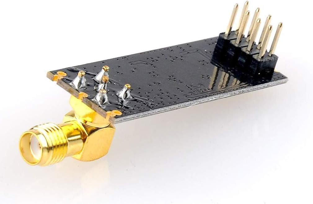
Figure 3: Pin Headers on the NRF24L01+PA+LNA Module.
3.3 Antenna Connection
The module comes with an SMA antenna. Carefully screw the antenna onto the SMA connector on the module. Ensure it is finger-tight to establish a good connection without over-tightening, which could damage the connector.
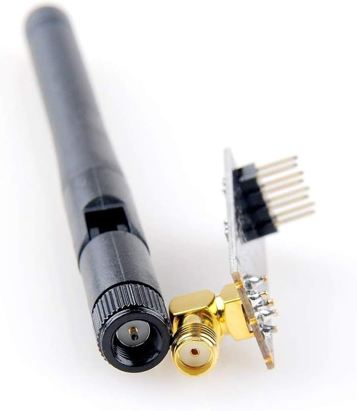
Figure 4: SMA Antenna Connector Detail.
4. Operating Instructions
Operating the NRF24L01+PA+LNA module involves configuring its internal registers via SPI to set up communication parameters. This typically includes:
- Setting Communication Channel: Choose one of the 125 available frequency channels. Both transmitting and receiving modules must be on the same channel.
- Configuring Data Rate: Select between 250kbps, 1Mbps, or 2Mbps. A lower data rate generally offers better range and reliability.
- Adjusting Output Power: The module allows adjustment of transmission power. Higher power increases range but consumes more current.
- Setting Up Addresses: Configure unique addresses for transmitting and receiving pipes.
- Enabling Enhanced ShockBurst: This feature provides automatic packet handling, including acknowledgements and retransmits, improving data reliability.
For detailed programming and library usage, refer to specific microcontroller development environments (e.g., Arduino IDE, ESP-IDF) and community resources. Many open-source libraries are available to simplify interaction with the nRF24L01 series modules.
5. Maintenance
The HiLetgo NRF24L01+PA+LNA module is designed for durability and requires minimal maintenance. To ensure optimal performance and longevity:
- Keep Dry: Protect the module from moisture and humidity, which can cause short circuits and corrosion.
- Avoid Physical Damage: Handle the module carefully to prevent bending pins, damaging the antenna connector, or cracking the PCB.
- Cleanliness: Keep the module free from dust and debris. Use a soft, dry brush or compressed air for cleaning if necessary.
- Proper Storage: When not in use, store the module in an anti-static bag to protect it from electrostatic discharge (ESD).
6. Troubleshooting
If you encounter issues with your HiLetgo NRF24L01+PA+LNA module, consider the following common troubleshooting steps:
- No Transmission/Reception:
- Insufficient Power: This is the most common issue. Ensure your 3.3V power supply can deliver sufficient current (up to 115mA during peak transmission). Add a large capacitor (e.g., 100uF) across VCC and GND.
- Incorrect Wiring: Double-check all SPI connections (CSN, SCK, MOSI, MISO, IRQ, CE) and power connections (VCC, GND).
- Antenna Not Connected: Verify the SMA antenna is securely attached.
- Software Configuration: Ensure both transmitter and receiver modules are configured with the same channel, data rate, and addresses. Check your code for proper initialization and communication logic.
- Limited Range:
- Antenna Orientation: Ensure antennas are oriented correctly for optimal signal propagation.
- Interference: Other 2.4GHz devices (Wi-Fi, Bluetooth) can cause interference. Try changing the communication channel.
- Output Power Setting: Verify the module's output power is set to maximum in your software configuration.
- Module Not Detected by Microcontroller:
- SPI Initialization: Confirm your microcontroller's SPI bus is correctly initialized.
- Power Supply: Ensure the module is receiving stable 3.3V power.
For complex issues, consult online forums, community resources, and the manufacturer's support channels. Providing detailed descriptions of your setup and observed behavior will assist in diagnosis.
7. Product Specifications
| Feature | Specification |
|---|---|
| Frequency | 2.4GHz ~ 2.5GHz (ISM Band) |
| Operating Voltage | 3V ~ 3.6V (Max) |
| Current (Max) | 115mA |
| Multi-frequency Channels | 125 selectable channels |
| Data Reception | Supports up to six channels of data reception |
| Interface | 4-pin Serial Peripheral Interface (SPI) |
| Input Tolerance | 5V tolerant SPI pins |
| Modulation | Gaussian Frequency-Shift Keying (GFSK) |
| Dimensions | 41mm x 15.5mm (approx. 1.61 x 0.61 inches) |
| Item Weight | 0.32 ounces |
| Model Number | 3-01-0781 |
8. Warranty and Support
HiLetgo products are typically covered by a standard manufacturer's warranty against defects in materials and workmanship. For specific warranty terms, technical support, or assistance with product issues, please refer to the official HiLetgo website or contact their customer service directly. Keep your purchase receipt for warranty claims.
For additional resources and community support, consider searching online forums and development communities dedicated to nRF24L01 modules and microcontroller projects.
Ask a question about this manual
Ask about setup, troubleshooting, compatibility, parts, safety, or missing instructions. Manuals+ will review the question and use this page’s manual context to help answer it.