MITSUBISHI ELECTRIC FX3U-64MR/ES FX3U Main Unit Instruction Manual
Model: FX3U-64MR/ES
1. Product Overview
This manual provides essential information for the safe and efficient operation of the MITSUBISHI ELECTRIC FX3U-64MR/ES FX3U Main Unit. The FX3U series is a high-performance programmable logic controller (PLC) designed for industrial automation applications.
The FX3U-64MR/ES model features an AC power supply and DC inputs, with a total of 64 integrated inputs/outputs. It includes 32 integrated DC inputs and 32 integrated relay outputs.
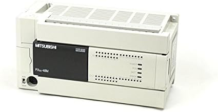
Figure 1: Front view of the MITSUBISHI ELECTRIC FX3U-64MR/ES Main Unit. This image displays the primary interface of the PLC, including the MITSUBISHI branding, model designation, and indicator lights for power, run, battery, and error status. Input and output terminal blocks are visible on the right side.
2. Safety Precautions
Always observe the following safety precautions to prevent electric shock, fire, or damage to the product. Failure to follow these instructions may result in injury or equipment malfunction.
- Ensure power is disconnected before performing any installation, wiring, or maintenance.
- Do not operate the unit in environments with excessive dust, corrosive gases, or high humidity.
- Ground the unit properly to prevent electrical hazards.
- Use only specified power supply voltages (100-240VAC).
- Refer to local and national electrical codes for installation requirements.
3. Setup and Installation
Proper installation is crucial for the reliable operation of the FX3U-64MR/ES main unit.
3.1 Mounting
The FX3U-64MR/ES unit is designed for DIN rail mounting or direct panel mounting. Ensure adequate space for ventilation around the unit.
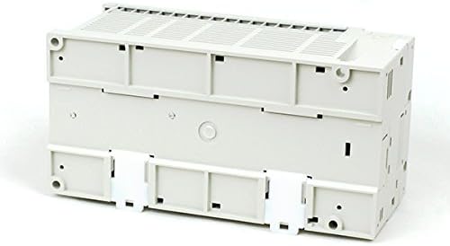
Figure 2: Bottom view of the FX3U-64MR/ES Main Unit. This image highlights the mounting features, including the clips for DIN rail attachment, which facilitate secure installation within an industrial control panel.
For DIN rail mounting, attach the unit securely to a standard 35mm DIN rail. For direct panel mounting, use appropriate screws through the designated mounting holes.
3.2 Wiring
All wiring should be performed by qualified personnel with power disconnected.
3.2.1 Power Supply Wiring
Connect the 100-240VAC power supply to the designated power terminals. Ensure correct polarity and proper grounding.
3.2.2 Input Wiring (DC Inputs)
Connect DC input devices (e.g., sensors, switches) to the input terminals (X0 to X31). Refer to the wiring diagram for specific terminal assignments.
3.2.3 Output Wiring (Relay Outputs)
Connect output devices (e.g., contactors, indicator lights) to the relay output terminals (Y0 to Y31). Observe the maximum current ratings for each output.
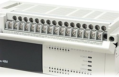
Figure 3: Close-up of the terminal blocks on the FX3U-64MR/ES. This detailed view shows the screw terminals for connecting input (X) and output (Y) wiring, along with their respective numbering, facilitating precise electrical connections.
4. Operating Instructions
The FX3U-64MR/ES operates based on a user-defined program. Programming is typically done using MITSUBISHI ELECTRIC's GX Works software.
4.1 Powering On
After completing all wiring and ensuring safety, apply power to the unit. The POWER indicator LED should illuminate.
4.2 Program Download and Execution
- Connect a programming device (e.g., PC) to the PLC's communication port.
- Use GX Works software to create or load the desired control program.
- Download the program to the FX3U-64MR/ES unit.
- Switch the PLC to RUN mode. The RUN indicator LED should illuminate.
Monitor the status indicators (POWER, RUN, BATT, ERROR) on the front panel for operational status.
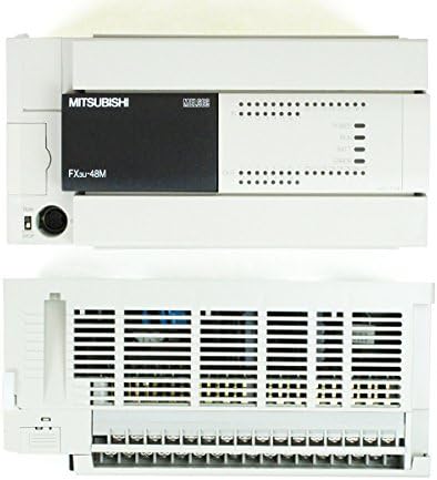
Figure 4: Top and front view of the FX3U-64MR/ES Main Unit. This perspective shows the ventilation grilles on the top surface, essential for heat dissipation, along with the front panel indicators and communication port.
5. Maintenance
Regular maintenance ensures the longevity and reliable performance of your FX3U-64MR/ES unit.
- Cleaning: Periodically clean the unit's exterior with a soft, dry cloth. Do not use solvents or abrasive cleaners. Ensure ventilation openings are free from dust and debris.
- Inspection: Regularly inspect wiring connections for looseness or damage. Check for any signs of overheating or unusual odors.
- Battery Replacement: The unit contains a battery for retaining program data during power outages. If the BATT indicator illuminates, replace the battery according to the manufacturer's instructions.
- Firmware Updates: Refer to MITSUBISHI ELECTRIC's official documentation for information on firmware updates.
6. Troubleshooting
This section provides solutions to common issues encountered with the FX3U-64MR/ES main unit.
| Problem | Possible Cause | Solution |
|---|---|---|
| POWER LED Off | No power supply, incorrect wiring, or internal fault. | Check power connections and voltage. Verify wiring. If problem persists, contact support. |
| ERROR LED On | Program error, hardware fault, or communication error. | Check program logic using GX Works. Inspect hardware for damage. Verify communication settings. |
| RUN LED Off (when expected On) | PLC in STOP mode, no program loaded, or program error. | Switch PLC to RUN mode. Download a valid program. Check for program errors. |
| Input/Output not responding | Incorrect wiring, faulty sensor/actuator, or program logic error. | Verify input/output wiring. Test external devices. Check program logic for correct I/O addressing. |
For more detailed troubleshooting, refer to the comprehensive MITSUBISHI ELECTRIC FX3U series programming and hardware manuals.
7. Specifications
Key technical specifications for the MITSUBISHI ELECTRIC FX3U-64MR/ES Main Unit:
- Model: FX3U-64MR/ES
- Integrated Inputs/Outputs: 64 points
- Integrated Inputs: 32 points (DC)
- Integrated Outputs: 32 points (Relay)
- Power Supply: 100-240VAC
- Power Consumption: 45W
- Weight: 1.00 kg (approx. 35.27 oz)
- Certifications: UL, cUL, CE (EMC)
- Item Model Number: FX3U 64MR
- Manufacturer: MITSUBISHI ELECTRIC
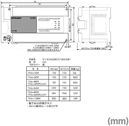
Figure 5: Technical drawing illustrating dimensions for various FX3U series models. This diagram provides critical measurements (W, W1, H) in millimeters, along with weight specifications, aiding in panel design and installation planning.
8. Warranty and Support
Warranty information for the MITSUBISHI ELECTRIC FX3U-64MR/ES is typically provided with the product packaging or can be obtained directly from MITSUBISHI ELECTRIC or an authorized distributor. Please retain your proof of purchase for warranty claims.
For technical support, programming assistance, or service, please contact your local MITSUBISHI ELECTRIC representative or visit the official MITSUBISHI ELECTRIC website for support resources and contact information.
Manufacturer: MITSUBISHI ELECTRIC
Brand: MITSUBISHI