1. Introduction
This manual provides detailed instructions for the installation, operation, and maintenance of the HSH-Flo 1-1/4 inch 3-Way Motorized Proportional Ball Valve. This valve is designed for precise flow control in various applications, including HVAC systems, heating systems, water treatment equipment, and industrial automation.
Please read this manual thoroughly before installation and operation to ensure proper function and safety.
2. Safety Information
- Ensure all power is disconnected before installation or maintenance.
- Installation should be performed by qualified personnel in accordance with local codes and regulations.
- Do not exceed the specified operating pressure or temperature limits.
- Protect the valve and actuator from physical damage and extreme environmental conditions.
- Verify correct wiring connections to prevent electrical hazards or damage to the unit.
3. Product Overview and Components
The HSH-Flo motorized ball valve consists of a brass valve body and an electric actuator. The actuator controls the ball's position within the valve body, allowing for proportional flow regulation.

Figure 3.1: Front view of the HSH-Flo 1-1/4 inch 3-Way Motorized Proportional Ball Valve. This image displays the orange and black actuator mounted on the brass valve body, with the electrical wiring harness visible on the right side.
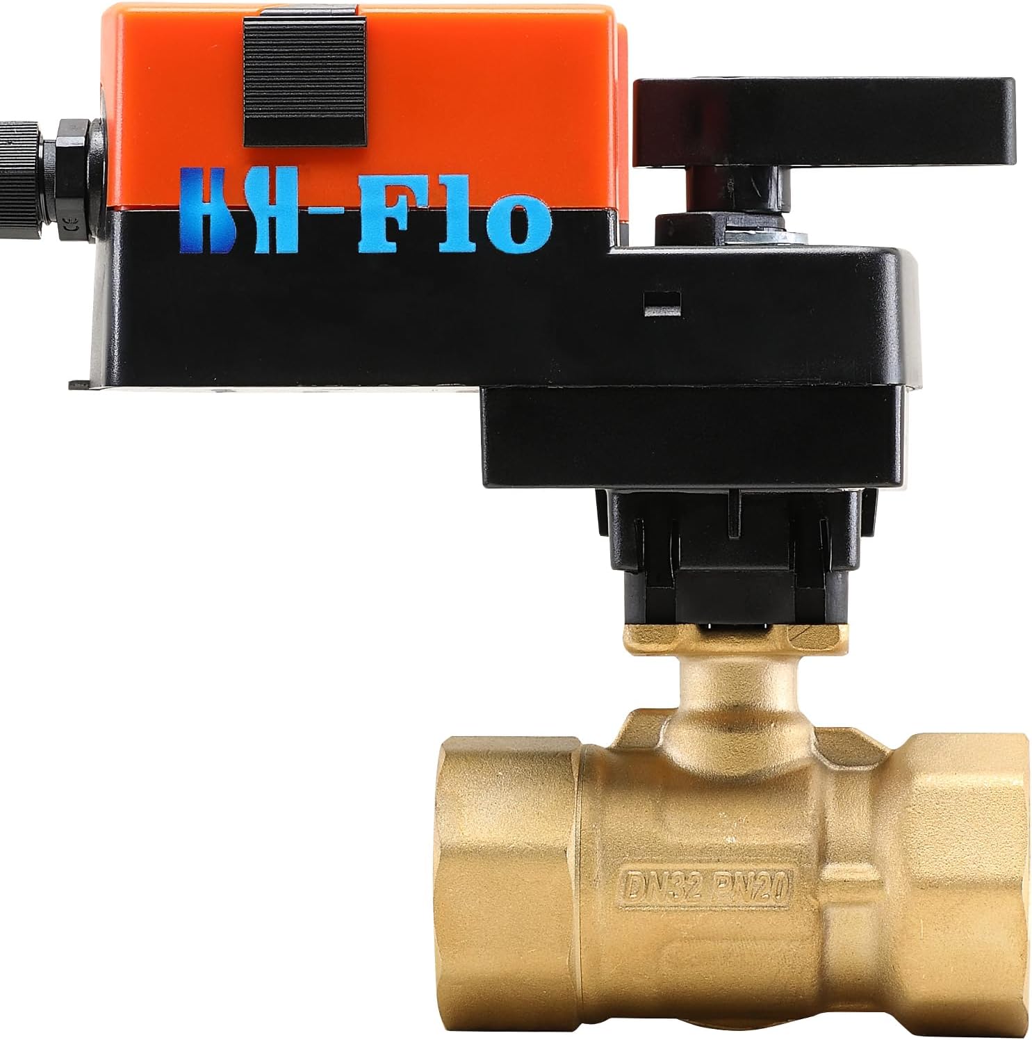
Figure 3.2: Side view of the HSH-Flo Motorized Ball Valve. This image highlights the manual override lever on the actuator, which can be used to operate the valve manually in case of power failure.
Key Components:
- Valve Body: Forged Brass (Hpb59-1) with 1-1/4 inch G/BSP internal thread pipe connections.
- Ball: Chrome-Plated Brass.
- Seal: EPDM+PTFE Ball, EPDM Stem.
- Actuator: Electric motor with 6 N.M output torque, 90° angle of rotation.
- Manual Handle: For manual operation during power outages or setup.
4. Specifications
Actuator Specifications:
| Power Supply | 24VAC/DC |
| Power Consumption | 6VA |
| Input Signal | 0-10V and 4-20mA (Dual Input) |
| Output Torque | 6 N.M |
| Angle of Rotation | 90° |
| Ambient Temperature | -5°C to 60°C |
| Ambient Humidity | 0-90% RH |
| Protection Rank | IP54 |
| Overload Protection | Automatic Overload Protection System |
Valve Body Specifications:
| Valve Size | 1-1/4 inch |
| Pipe Connection | G/BSP Internal Thread (BSPT) |
| Medium | Cold/Hot Water, with 50% Glycol |
| Temperature of Medium | 2°C to 90°C |
| Rated Pressure | 290 Psi (2.0Mpa) |
| Valve Type | 3-Way |
| Cv Value | 18.67 Gal/Hours |
5. Setup and Installation
5.1 Mounting the Valve
- Ensure the piping system is depressurized and drained before installation.
- Install the valve in a location that allows for easy access for wiring, operation, and maintenance.
- Connect the 1-1/4 inch G/BSP internal threads of the valve body to the corresponding pipe connections. Use appropriate sealing tape or compound to ensure a leak-free connection.
- Ensure the valve is installed in the correct flow direction as indicated by any markings on the valve body (if present).
5.2 Electrical Wiring
The actuator requires a 24VAC/DC power supply and accepts either a 0-10V or 4-20mA input signal for proportional control. Refer to the wiring diagram on the actuator label for precise connections.

Figure 5.1: Detailed view of the wiring diagram and specifications label on the HSH-Flo actuator. This diagram shows connections for power (AC/DC 24V) and control signals (DC0(4)...20mA, DC0(2)...10V).
- Power Connection: Connect the 24VAC/DC power supply to the designated terminals on the actuator.
- Control Signal Connection: Connect the 0-10V or 4-20mA control signal from your controller to the appropriate input terminals. Ensure correct polarity for DC signals.
- Grounding: Ensure proper grounding according to local electrical codes.
- After wiring, secure all connections and ensure the actuator cover is properly closed to maintain IP54 protection.
6. Operating Instructions
6.1 Automatic Operation
Once powered and connected to a control system, the actuator will respond to the input signal (0-10V or 4-20mA) to proportionally position the valve. A 0V/4mA signal typically corresponds to a fully closed position, while a 10V/20mA signal corresponds to a fully open position, or vice-versa depending on configuration.
- Apply power to the actuator. The valve will move to its position dictated by the control signal.
- Monitor the system to ensure the valve is operating as expected and providing the desired flow control.
6.2 Manual Override
In the event of a power failure or for maintenance purposes, the valve can be operated manually using the manual handle on the actuator.
- Ensure power to the actuator is disconnected before attempting manual override.
- Locate the manual override lever/handle on the actuator (refer to Figure 3.2).
- Engage the manual override mechanism (e.g., by pushing down or rotating a lever).
- Rotate the handle to open or close the valve as required.
- After manual operation, disengage the manual override mechanism to allow for automatic control when power is restored.
7. Maintenance
The HSH-Flo motorized ball valve is designed for minimal maintenance. However, periodic checks are recommended to ensure optimal performance and longevity.
- Visual Inspection: Regularly inspect the valve and actuator for any signs of leaks, corrosion, or physical damage.
- Electrical Connections: Periodically check electrical connections for tightness and ensure wiring is intact and free from wear.
- Actuator Function: Verify that the actuator moves smoothly through its full range of motion in response to control signals.
- Cleaning: Keep the exterior of the actuator clean and free from dust or debris. Do not use harsh chemicals.
- Seal Integrity: If leaks are detected around the valve stem or connections, inspect seals and replace if necessary (contact support for replacement parts).
8. Troubleshooting
| Problem | Possible Cause | Solution |
|---|---|---|
| Valve does not move | No power to actuator; Incorrect wiring; Actuator fault; Control signal issue. | Check power supply (24VAC/DC); Verify wiring connections against diagram; Check control signal (0-10V or 4-20mA) from controller; Test manual override. |
| Valve leaks | Loose pipe connections; Damaged valve seals. | Tighten pipe connections; Inspect and replace valve seals if damaged (contact support). |
| Valve does not fully open/close | Incorrect calibration; Obstruction in valve; Actuator limit switch issue. | Verify control signal range; Check for debris in the valve; Contact support if actuator limits seem faulty. |
| Actuator makes unusual noise | Internal mechanical issue; Overload. | Disconnect power and inspect for obstructions; If noise persists, contact support. |
9. Warranty and Support
HSH-Flo products are manufactured to high-quality standards. For specific warranty information, please refer to the documentation provided with your purchase or visit the official HSH-Flo website.
For technical assistance, troubleshooting beyond this manual, or to inquire about replacement parts, please contact HSH-Flo customer support. When contacting support, please have your model number (WN-3J32-306B) and purchase date available.
HSH-Flo Customer Support: Visit the HSH-Flo Store on Amazon