1. Introduction
This instruction manual provides essential information for the safe and efficient installation, operation, and maintenance of the KB ELECTRONICS KBRG-240D Regenerative DC Motor Control Drive. Please read this manual thoroughly before attempting to install or operate the unit. Retain this manual for future reference.
The KBRG-240D is a regenerative DC motor control designed for industrial applications, offering precise control over DC motors with regenerative braking capabilities.
2. Safety Information
WARNING: Electrical Hazard. Risk of electric shock. Disconnect all power before servicing.
- Installation and servicing must be performed by qualified personnel only.
- Ensure the power supply matches the unit's specifications.
- Always ground the unit properly to prevent electrical shock.
- Do not operate the control with covers removed.
- Protect the unit from moisture, dust, and corrosive environments.
3. Product Overview
The KBRG-240D is a robust DC motor control unit. Below are images illustrating the main components and identification labels.
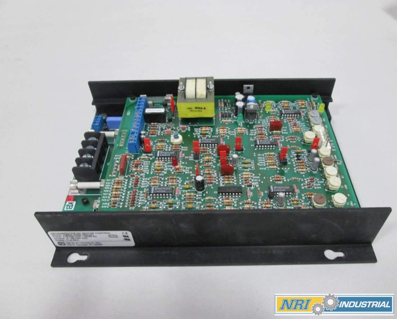
Figure 3.1: Overall view of the KBRG-240D Regenerative DC Motor Control Drive, showing the main circuit board with various electronic components, including resistors, capacitors, integrated circuits, and a transformer, mounted on a heat-dissipating chassis.

Figure 3.2: Product identification label for the KBRG-240D, indicating "REGENERATIVE DC MOTOR CONTROL", Model: KBRG-240D (8802A), Input: 115/230 VAC - 50/60 Hz, Output: 0-90/180 VDC, and Rated: 11.0 ADC. The label also shows "KB ELECTRONICS, INC." and compliance marks.

Figure 3.3: Side view of the control unit, highlighting the terminal blocks for electrical connections. Visible are terminals labeled F+, F- (field), L1, L2 (AC input), and M1, M2 (DC motor output), along with associated fuses and a multi-pin connector for control signals.

Figure 3.4: Close-up of the KBRG-240D circuit board, revealing the intricate arrangement of electronic components. This view shows various integrated circuits (e.g., LM324N), resistors, capacitors, and diodes, which are crucial for the drive's control logic and power regulation.
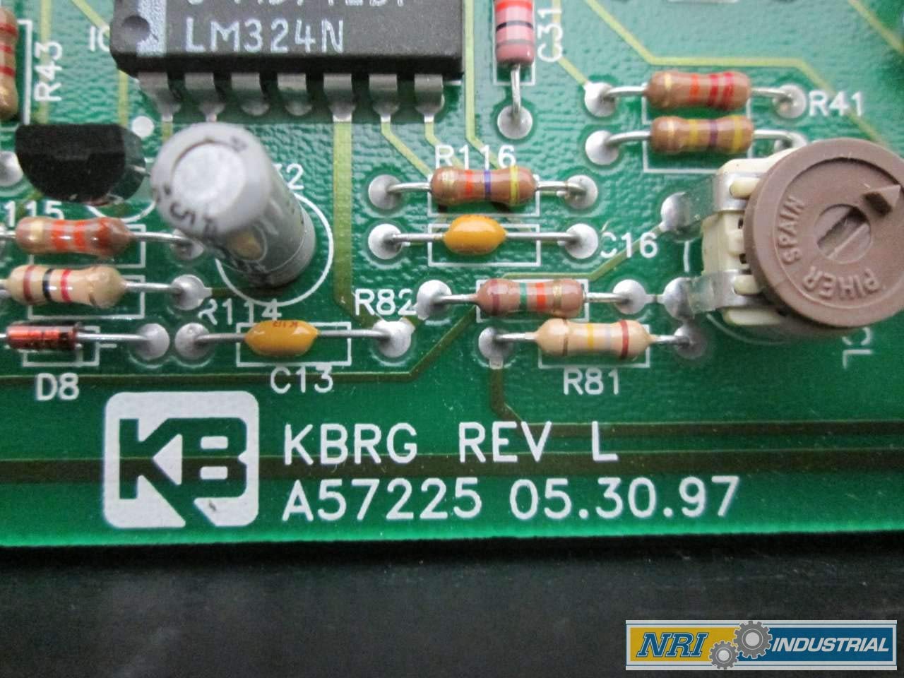
Figure 3.5: Detail of the circuit board showing the KB logo and the revision information: "KBRG REV L A57225 05.30.97". This indicates the specific hardware revision and manufacturing date of the board.

Figure 3.6: Top view of the circuit board, highlighting a row of adjustment potentiometers (trimpots) labeled for functions such as FWD (Forward), REV (Reverse), ACCEL (Acceleration), DB (Deceleration Brake), SPD (Speed), COMP (Compensation), and IR (IR Compensation). These allow for calibration and fine-tuning of the motor drive's performance.

Figure 3.7: A product label with a barcode, identifying the unit as "KB ELECTRONICS KBRG-240D PENTA POWER DC 115/230V-AC 0-90/180V-DC 60HZ 11A AMP MOTOR DRIVE". It also displays the part number 353576 and SKU D270272 (GMF).
4. Specifications
| Parameter | Value |
|---|---|
| Model | KBRG-240D (8802A) |
| Output Power | 2 HP |
| Input Voltage | 115/230 V-AC |
| Output Voltage | 0-90/180 V-DC |
| Input Frequency | 50/60 Hz |
| Rated Current | 11.0 ADC |
| Product Dimensions | 12 x 9.75 x 4.5 inches |
| Manufacturer | KB ELECTRONICS |
| SKU | D270272 (GMF) |
| Part Number | 353576 |
5. Setup and Installation
Proper installation is critical for the safe and reliable operation of the KBRG-240D. Refer to the wiring diagrams and instructions provided with the unit for specific connection details. The following are general guidelines:
- Mounting: Mount the control unit in a clean, dry, and well-ventilated enclosure. Ensure adequate clearance for cooling and access to terminals.
- Power Wiring: Connect the AC input power (L1, L2) to the designated terminals. Ensure the voltage matches the unit's rating (115V or 230V).
- Motor Wiring: Connect the DC motor armature (M1, M2) and field (F+, F-) leads to the appropriate terminals. Observe polarity.
- Grounding: Connect the chassis ground terminal to a reliable earth ground.
- Control Wiring: Connect any external control signals (e.g., speed potentiometer, start/stop switches) to the control terminal block as per the specific application requirements.
- Initial Checks: Before applying power, double-check all wiring connections for correctness and tightness.
CAUTION: Incorrect wiring can damage the unit and connected equipment.
6. Operating Instructions
The KBRG-240D provides regenerative braking, allowing for rapid deceleration and energy return to the AC line. Operation typically involves setting the desired speed and initiating motor movement.
- Power On: Apply AC power to the control unit.
- Speed Adjustment: Use the external speed potentiometer or control signal to set the desired motor speed.
- Start/Stop: Activate the start command (e.g., close a contact) to begin motor rotation. Deactivate the command to stop.
- Direction Control: If configured for reversible operation, use the appropriate control signals to select forward or reverse direction.
- Acceleration/Deceleration: The acceleration and deceleration ramps can be adjusted via internal potentiometers (refer to Figure 3.6) to suit application requirements, ensuring smooth motor starts and stops.
For optimal performance, refer to the detailed calibration procedures in the full technical manual for adjusting internal potentiometers like IR Compensation, Current Limit, and Stability.
7. Maintenance
The KBRG-240D is designed for reliable operation with minimal maintenance. However, periodic checks can extend its lifespan and ensure continued performance.
- Cleaning: Keep the unit and its enclosure clean and free from dust, dirt, and debris. Use compressed air to gently remove dust from the circuit board.
- Connections: Periodically check all electrical connections for tightness. Loose connections can cause overheating and intermittent operation.
- Ventilation: Ensure that ventilation openings are not obstructed to allow for proper heat dissipation.
- Visual Inspection: Inspect the circuit board for any signs of discoloration, burnt components, or damaged wiring.
WARNING: Disconnect all power before performing any maintenance.
8. Troubleshooting
This section provides general guidance for common issues. For complex problems, consult a qualified technician or KB ELECTRONICS support.
| Problem | Possible Cause | Solution |
|---|---|---|
| Motor does not start | No input power; Blown fuse; Incorrect control signal; Motor wiring error. | Check power supply; Replace fuses (after identifying cause); Verify control signal connections; Inspect motor wiring. |
| Motor runs erratically | Loose connections; Interference; Incorrect potentiometer settings. | Check all wiring; Ensure proper shielding; Recalibrate potentiometers. |
| Overheating | Insufficient ventilation; Overload; Short circuit. | Ensure clear airflow; Reduce load; Check for shorts in motor or wiring. |
9. Warranty and Support
For warranty information, please refer to the documentation provided at the time of purchase or contact KB ELECTRONICS directly. Technical support can be obtained through authorized distributors or the manufacturer's official website.
Manufacturer: KB ELECTRONICS, INC.
Address: Coral Springs, FL 33065