1. Introduction
This manual provides essential information for the safe and effective installation, operation, and maintenance of the Square D 8536-SD01 Series A Motor Starter. This device is designed to control the starting and stopping of electric motors in various industrial applications, offering reliable performance and protection.
Please read this manual thoroughly before attempting any installation or operation procedures. Retain this manual for future reference.
2. Important Safety Information
WARNING: ELECTRICAL SHOCK HAZARD
- Installation, adjustment, and maintenance must be performed by qualified electrical personnel only.
- Always disconnect and lock out all power sources before working on the motor starter or associated equipment. Failure to do so can result in severe injury or death.
- Ensure all local and national electrical codes are followed during installation and operation.
- Do not operate the starter with damaged components or wiring.
3. Product Overview and Components
The Square D 8536-SD01 Series A Starter is a robust industrial component. It typically consists of a contactor for switching motor power and an overload relay for motor protection against overcurrent conditions.

Figure 3.1: Front view of the Square D 8536-SD01 Series A Motor Starter. This image displays the main body of the starter, including the contactor and overload relay assembly, with visible power terminals and control wiring points.
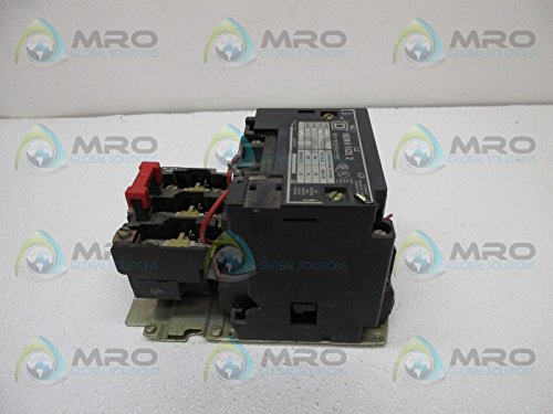
Figure 3.2: Side view of the Square D 8536-SD01 Series A Motor Starter. This perspective highlights the depth and mounting points of the unit, showing the robust construction and terminal block arrangement.

Figure 3.3: Close-up view of the identification label on the Square D 8536-SD01 Series A Motor Starter. The label provides critical technical specifications such as NEMA size, class, type, form, series, and three-phase voltage/horsepower ratings.
4. Setup and Installation
Proper installation is crucial for the safe and reliable operation of the motor starter.
4.1 Mounting
- Mount the starter securely to a rigid, vibration-free surface using appropriate fasteners.
- Ensure adequate clearance for ventilation and access to wiring terminals.
- Install in an environment free from excessive dust, moisture, corrosive gases, and extreme temperatures.
4.2 Wiring
- Refer to the wiring diagram provided with the unit or on the product label for correct connections.
- Connect the main power supply to the L1, L2, L3 terminals.
- Connect the motor leads to the T1, T2, T3 terminals.
- Connect the control circuit wiring (e.g., start/stop buttons, auxiliary contacts) to the designated control terminals.
- Ensure all connections are tight and secure to prevent loose contacts and overheating.
4.3 Overload Relay Adjustment
- Set the overload relay current adjustment dial to the motor's full-load ampere (FLA) rating, as specified on the motor nameplate.
- This setting provides thermal protection for the motor against sustained overcurrents.
5. Operation
Once properly installed and wired, the motor starter is ready for operation.
5.1 Starting the Motor
- Ensure all safety precautions are observed and the area around the motor is clear.
- Activate the start button or control signal. The contactor will energize, closing its main contacts and supplying power to the motor.
- The motor should start and run.
5.2 Stopping the Motor
- Activate the stop button or remove the control signal. The contactor will de-energize, opening its main contacts and removing power from the motor.
- The motor will stop.
5.3 Overload Trip and Reset
- If the motor draws current exceeding the overload relay setting for a prolonged period, the overload relay will trip, opening the control circuit and stopping the motor.
- To reset a tripped overload, first identify and correct the cause of the overload (e.g., mechanical binding, low voltage).
- Allow the overload relay to cool down for a few minutes.
- Press the reset button on the overload relay.
6. Maintenance
Regular maintenance helps ensure the longevity and reliable operation of your motor starter.
6.1 Routine Inspection (Quarterly/Annually)
- Visual Check: Inspect for signs of overheating (discoloration), loose connections, damaged insulation, or excessive dust/debris.
- Tightness Check: Verify that all power and control wiring connections are tight.
- Contact Inspection: If accessible, inspect the contactor contacts for excessive pitting or wear. Replace if necessary.
- Mechanical Operation: Manually operate the contactor (with power disconnected) to ensure smooth mechanical movement.
6.2 Cleaning
- With power disconnected, use a dry, clean cloth or a vacuum cleaner to remove any accumulated dust or debris from the starter and its enclosure.
- Do not use solvents or abrasive cleaners.
7. Troubleshooting
This section provides guidance for common issues. Always ensure power is disconnected before performing any inspection or repair.
| Problem | Possible Cause | Solution |
|---|---|---|
| Motor does not start when 'Start' button is pressed. |
|
|
| Motor trips immediately after starting. |
|
|
| Contactor hums loudly. |
|
|
8. Technical Specifications
The following specifications apply to the Square D 8536-SD01 Series A Motor Starter:
| Specification | Value |
|---|---|
| Brand | Square D |
| Model Number | 8536-SD01 |
| Series | A |
| NEMA Size | 2 |
| Class | 8536 |
| Type | SD0 1 |
| Form | S |
| Maximum Voltage | 600 Volts |
| Three-Phase Rating (200V) | 10 HP |
| Three-Phase Rating (230V) | 15 HP |
| Three-Phase Rating (380/460/575V) | Not specified on label, typically higher HP for higher voltage. Refer to specific unit label. |
| Material | Metal |
| Item Weight | 29 Pounds |
| Product Dimensions (L x W x H) | 20 x 14 x 14 inches |
| Manufacturer | Square D |
| ASIN | B00RW792DA |
9. Warranty Information
Square D products are typically covered by a manufacturer's warranty against defects in materials and workmanship. The specific terms and duration of the warranty may vary by region and product. Please refer to the official Square D website or contact their customer support for detailed warranty information applicable to your purchase.
10. Customer Support
For technical assistance, troubleshooting beyond this manual, or inquiries regarding parts and service, please contact Square D customer support. You can find contact information on the official Square D website or through your local distributor.
When contacting support, please have your product model number (8536-SD01) and any relevant serial numbers ready.


