1. Introduction
This manual provides essential information for the safe and efficient operation of your COTEK SP-1000-112 Pure Sine Wave Inverter. Please read all instructions carefully before installation and use. The SP-1000-112 is designed to convert 12VDC battery power into 120VAC pure sine wave electricity, suitable for sensitive electronics and various AC appliances.
Key Features:
- Pure sine wave output for clean, stable power.
- Power ON / OFF remote control capability (Green Terminal).
- Input & output are fully isolated for enhanced safety.
- Temperature & load controlled cooling fan for optimal performance.
- User-friendly interface.
- Type 1 Indoor Aluminum Enclosure.

Figure 1: COTEK SP-1000-112 Pure Sine Wave Inverter, front-side view. This image shows the overall design of the COTEK SP-1000-112 Pure Sine Wave Inverter, highlighting its compact form factor and blue casing.
2. Safety Information
Always observe the following safety precautions to prevent injury and damage to the inverter or connected equipment.
- Electrical Hazard: High voltage is present inside the inverter when connected to a battery. Do not open the inverter casing.
- Proper Ventilation: Ensure adequate ventilation around the inverter to prevent overheating. Do not block ventilation openings.
- Dry Location: Install the inverter in a dry environment, away from water, moisture, and corrosive substances.
- Battery Safety: Work in a well-ventilated area when connecting batteries. Batteries can produce explosive gases. Wear appropriate personal protective equipment.
- Grounding: The inverter must be properly grounded. Follow all local and national electrical codes.
- Load Capacity: Do not exceed the inverter's rated output power. Overloading can cause damage and fire hazards.
- California Proposition 65 Warning: This product may contain materials cautioned by California Proposition 65.

Figure 2: Safety equipment for electrical work. Image depicting essential safety gear such as a hard hat, safety glasses, and work gloves, emphasizing the importance of personal protective equipment during installation and maintenance.
3. Setup and Installation
Follow these steps for proper installation of your SP-1000-112 inverter.
3.1 Mounting the Inverter
- Choose a secure, dry, and well-ventilated location.
- Ensure sufficient clearance around the inverter for airflow, especially around the cooling fan vents.
- Mount the inverter horizontally on a stable surface using appropriate fasteners.
3.2 DC Input Connection
Connect the inverter directly to a 12VDC battery bank. Use appropriately sized cables to minimize voltage drop and ensure safe operation.
- Ensure the inverter's power switch is in the OFF position.
- Connect the positive (+) DC cable from the battery to the positive (+) terminal on the inverter.
- Connect the negative (-) DC cable from the battery to the negative (-) terminal on the inverter.
- Secure all connections tightly.

Figure 3: Rear panel of COTEK SP-1000-112 Inverter. The rear panel includes the DC input terminals for battery connection, a ground lug, and a green terminal block for remote control and monitoring connections.
3.3 AC Output Connection
The inverter features two GFCI 120VAC outlets for connecting your AC appliances.
- Ensure the inverter is powered off before connecting any AC loads.
- Plug your AC appliances directly into the GFCI outlets on the front panel.
- Do not exceed the inverter's continuous power rating of 1000W.

Figure 4: Front panel of COTEK SP-1000-112 Inverter. The front panel features two GFCI 120VAC outlets, a power ON/OFF switch, and LED indicators for operational status and fault conditions. DIP switches for configuration are also visible.
3.4 Remote Control Connection (Optional)
The inverter supports an optional remote control via the green terminal block on the rear panel. Refer to the remote control's specific instructions for wiring details.
4. Operating Instructions
4.1 Powering On/Off
- After all connections are secure, switch the inverter's power switch to the ON position.
- The LED indicators will illuminate to show operational status.
- To power off, switch the power switch to the OFF position.
4.2 Power Saving Mode
The SP-1000-112 features an adjustable power saving mode, which can be configured via DIP switches. This mode reduces power consumption when no load or a very light load is detected, helping to conserve battery energy.

Figure 5: Light bulb illustrating power saving mode. A light bulb glowing, symbolizing the inverter's power saving mode feature which optimizes energy consumption for lighter loads.
4.3 GFCI Outlets
The integrated Ground Fault Circuit Interrupter (GFCI) outlets provide protection against electrical shock. If a ground fault is detected, the GFCI will trip, cutting power to the outlets. To reset, press the 'RESET' button on the outlet.

Figure 6: RV park at night, powered by inverter. An image of an RV park illuminated at night, demonstrating a typical application where the inverter provides reliable power for various appliances.
5. Maintenance
Regular maintenance ensures the longevity and reliable operation of your inverter.
- Cleaning: Periodically clean the exterior of the inverter with a dry cloth. Ensure ventilation openings are free from dust and debris. Do not use liquid cleaners.
- Connections: Annually inspect all DC and AC connections for tightness and corrosion. Loose connections can cause overheating and poor performance.
- Fan Operation: The cooling fan is temperature and load controlled. Ensure it operates freely when needed. If the fan becomes excessively noisy or stops working, contact support.
6. Troubleshooting
This section addresses common issues you might encounter with your inverter.
6.1 LED Indicators
The inverter features LED indicators to communicate its status:
- Green LED: Normal operation.
- Yellow/Orange LED: Warning condition (e.g., low battery voltage, high temperature).
- Red LED: Fault condition (e.g., overload, short circuit, over temperature, input over/under voltage). The inverter will typically shut down in this state.
6.2 Common Issues and Solutions
- No AC Output:
- Check if the inverter is powered on.
- Verify DC input connections are secure and battery voltage is within operating range.
- Check if the GFCI outlets have tripped. Press the 'RESET' button.
- Look for fault indicators (Red LED).
- Inverter Shuts Down:
- Overload: Reduce the connected AC load. The inverter has overload protection.
- Low Battery Voltage: Recharge or replace the battery. The inverter will shut down to protect the battery from deep discharge.
- Over Temperature: Ensure adequate ventilation. Allow the inverter to cool down. The fan should be operating.
- Input Over/Under Voltage: Verify the battery voltage is stable and within the specified input range (10.5-16.5VDC for 12V models).
- GFCI Trips Frequently:
- This can indicate a ground fault in the connected appliance or wiring. Disconnect appliances one by one to identify the faulty device.
- Ensure the inverter is properly grounded.
- A faulty appliance drawing excessive current can also trip the GFCI.
7. Specifications
Detailed technical specifications for the COTEK SP-1000-112 Pure Sine Wave Inverter.
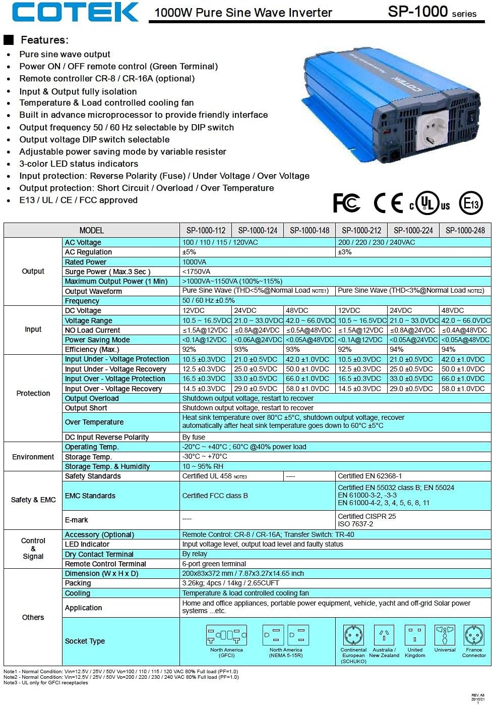
Figure 7: Technical specifications table for COTEK SP-1000 series inverters. This table provides comprehensive technical specifications for the SP-1000 series, including AC voltage, wattage, surge power, frequency, input voltage range, efficiency, and protection features.

Figure 8: Mechanical drawings and performance curves for COTEK SP-1000 series inverters. This image displays detailed mechanical dimensions of the inverter, along with power voltage and power temperature curves illustrating performance characteristics under various conditions.
| Feature | Specification |
|---|---|
| Brand | COTEK |
| Model Name | Cotek SP-1000-112 1000 Watt 110 Volt AC 12 Volt DC Pure Sine Inverter |
| Recommended Uses | Vehicle |
| Power Source | Battery Powered |
| Wattage (Continuous) | 1000 watts |
| Input Voltage | 12 Volts DC |
| Output Power | 1000 Watts AC |
| Number of Outlets | 2 (GFCI) |
| Frequency | 60 Hz |
| Standby Power Shutoff | High Efficiency |
| Item Weight | 9 Pounds |
| Color | Blue |
| UPC | 810308000592 |
| Mfr Part Number | SP-1000-112 |
8. Warranty Information
The COTEK SP-1000-112 Pure Sine Wave Inverter comes with a 2 Year Manufacturer Warranty. Please retain your proof of purchase for warranty claims. For specific terms and conditions, refer to the warranty documentation provided with your product or contact COTEK customer support.
9. Customer Support
For technical assistance, troubleshooting beyond this manual, or warranty inquiries, please contact COTEK customer support. Refer to the manufacturer's official website or product packaging for the most current contact information.
Manufacturer: Cotek