Introduction
This manual provides essential information for the proper installation, operation, and maintenance of the Honeywell PV075S Hydronic Air Vent. Please read these instructions carefully before installation and keep them for future reference. The PV075S is designed to automatically purge air from hydronic heating and cooling systems, ensuring efficient and quiet operation.
Safety Information
Always observe the following safety precautions to prevent personal injury and property damage:
- Ensure the system is depressurized and cooled before attempting any installation or maintenance.
- Wear appropriate personal protective equipment (PPE), such as safety glasses and gloves.
- Installation should be performed by a qualified professional in accordance with local codes and regulations.
- Do not modify the air vent in any way.
- Keep children away from the installation area.
Product Overview
The Honeywell PV075S is a high-capacity automatic air vent constructed from durable bronze. It features a float-operated mechanism that releases accumulated air from hydronic systems.

Figure 1: Main view of the Honeywell PV075S Hydronic Air Vent. This image shows the bronze body of the vent with its top cap and air release mechanism.
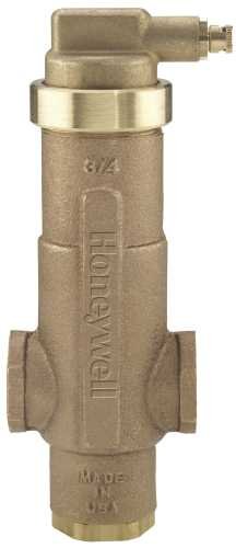
Figure 2: Detailed view of the Honeywell PV075S Hydronic Air Vent. This image highlights the upper section of the vent, including the manual vent screw and the "Honeywell" branding on the side.
Setup and Installation
Follow these steps for proper installation of the PV075S air vent:
- System Preparation: Ensure the hydronic system is completely drained and depressurized. Allow the system to cool down to a safe temperature.
- Location: Install the air vent at the highest point(s) of the hydronic system where air naturally collects. Common locations include boiler headers, high points in piping runs, and heat exchangers.
- Orientation: The PV075S must be installed in an upright, vertical position with the vent cap facing upwards.
- Connection: The PV075S uses sweat connections. Clean and prepare the pipe ends and the vent connections according to standard plumbing practices for sweat soldering.
- Soldering: Apply flux to the pipe and fitting, then solder the vent into place using appropriate solder and heat. Avoid overheating the vent body.
- Filling the System: After installation, slowly refill the hydronic system. As the system fills, the automatic air vent will begin to purge air.
- Vent Cap: Ensure the manual vent cap (small screw on top) is slightly loosened (typically one or two turns counter-clockwise) to allow automatic air purging. Do not remove it completely unless performing manual venting.
- Leak Check: Once the system is filled and pressurized, carefully inspect all connections for leaks.
Operating Instructions
The Honeywell PV075S is designed for automatic operation:
- Automatic Air Purging: With the system operating and the vent cap slightly loosened, air accumulating in the vent will cause the internal float to drop, opening a valve and releasing the air. As water fills the vent, the float rises, closing the valve. This process occurs continuously as needed.
- Manual Venting: If excessive air is present or for initial system fill, the vent cap can be manually loosened further to rapidly release air. Once water begins to escape, tighten the cap slightly to allow automatic operation. Do not overtighten.
Maintenance
The PV075S is largely maintenance-free, but periodic checks are recommended:
- Annual Inspection: Annually inspect the vent for any signs of leaks, corrosion, or damage.
- Vent Cap Check: Ensure the manual vent cap is not overtightened, which would prevent automatic air release. It should be slightly loose.
- Cleaning: If the vent appears to be clogged or not functioning, it may be necessary to clean the internal mechanism. This typically requires shutting down and draining the system. Consult a qualified technician for internal cleaning or replacement.
Troubleshooting
| Problem | Possible Cause | Solution |
|---|---|---|
| Air in system after installation | Vent cap overtightened; air pocket not reaching vent; vent malfunction. | Loosen vent cap slightly. Ensure vent is at highest point. Manually vent. If problem persists, inspect or replace vent. |
| Water leaking from vent cap | Vent cap too loose; debris in valve seat; vent malfunction. | Tighten vent cap slightly. If leak continues, system may need to be drained and vent inspected for debris or replaced. |
| Vent not releasing air | Vent cap closed; internal float mechanism stuck or fouled. | Ensure vent cap is slightly open. If still not working, system may need to be drained and vent inspected for internal issues or replaced. |
Specifications
| Feature | Detail |
|---|---|
| Brand | Honeywell |
| Model | PV075S |
| Material | Bronze |
| Connection Type | Sweat |
| UPC | 085267827867 |
| Manufacturer | Honeywell |
| Number of Items | 1 |
Note: "Power Connector Type", "Cooling Method", "Compatible Devices", and "Maximum Rotational Speed" from the source data appear to be generic or incorrect specifications for a hydronic air vent and have been excluded for accuracy.
Warranty and Support
For specific warranty information regarding the Honeywell PV075S Hydronic Air Vent, please refer to the official Honeywell website or contact Honeywell customer support directly. Warranty terms and conditions may vary.
For technical assistance or further inquiries, please visit the Honeywell Store on Amazon or the official Honeywell support channels.


