
Milwaukee 2212-20
Milwaukee 2212-20 Auto Voltage/Continuity Tester Instruction Manual
Model: 2212-20
1. Introduction
This manual provides essential information for the safe and effective operation of your Milwaukee 2212-20 Auto Voltage/Continuity Tester. Please read these instructions carefully before use and retain them for future reference.
2. Safety Information
WARNING: Always follow basic safety precautions when using electrical testing equipment to reduce the risk of fire, electric shock, and personal injury.
- Do not use the tester if it appears damaged or is operating abnormally.
- Ensure test leads are in good condition, free from cracks or breaks in insulation.
- Always verify the tester's operation on a known live circuit before testing an unknown circuit.
- Adhere to all local and national safety codes.
- Wear appropriate personal protective equipment (PPE), such as safety glasses and insulated gloves.
- Do not exceed the maximum voltage rating of the tester (CAT IV 600V).
3. Product Overview
The Milwaukee 2212-20 is an automatic voltage and continuity tester designed for ease of use and durability. It automatically detects AC or DC voltage and provides continuity indication.
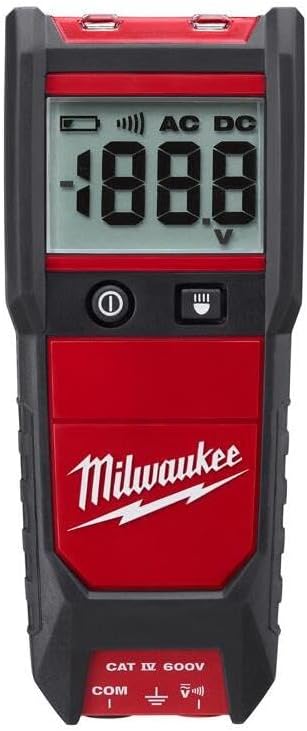
Figure 1: Front view of the Milwaukee 2212-20 Auto Voltage/Continuity Tester, showing the digital display, power button, and backlight button.
Components:
- Digital Display: Shows voltage readings (AC/DC) and continuity status.
- Power Button (ⓘ): Turns the tester on and off.
- Backlight Button (≡): Activates the display backlight for improved visibility in low-light conditions.
- Test Lead Input Jacks: Connect the red and black test leads.
- Test Leads: Red (positive) and Black (common) leads with probes.

Figure 2: Contents of the Milwaukee 2212-20 kit, including the auto voltage/continuity tester and electrical test lead set.
4. Setup
4.1 Battery Installation
The Milwaukee 2212-20 requires two AAA batteries for operation. These are typically included with the kit.
- Locate the battery compartment on the rear of the tester.
- Use a screwdriver to open the battery compartment cover.
- Insert two AAA batteries, observing the correct polarity (+/-) as indicated inside the compartment.
- Replace the battery compartment cover and secure it with the screw.
Note: Remove batteries if the tester will not be used for an extended period to prevent leakage.
4.2 Connecting Test Leads
Connect the test leads to the appropriate input jacks on the tester.
- Insert the red test lead into the VΩ input jack (positive).
- Insert the black test lead into the COM input jack (common/negative).
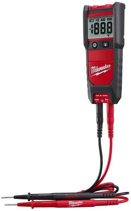
Figure 3: The Milwaukee 2212-20 tester with red and black test leads properly connected to the input jacks.
5. Operating Instructions
5.1 Powering On/Off
Press the Power button (ⓘ) to turn the tester on. Press and hold the Power button for approximately 2 seconds to turn it off. The tester may also feature an auto-off function to conserve battery life.
5.2 Automatic Voltage Testing (AC/DC)
The 2212-20 automatically detects and displays AC or DC voltage.
- Ensure the tester is powered on.
- Carefully touch the red test probe to the positive or live point of the circuit and the black test probe to the negative or neutral/ground point.
- The display will show the detected voltage and indicate whether it is AC or DC.
Always test on a known live circuit first to confirm the tester is functioning correctly.
5.3 Continuity Testing
The tester provides an audible and visual indication for continuity.
- Ensure the circuit or component to be tested is de-energized.
- Touch the red and black test probes to the two points you wish to test for continuity.
- If continuity exists (low resistance), the tester will emit an audible beep and the display may show a continuity symbol or a low resistance value.
5.4 Backlight Function
Press the Backlight button (≡) to illuminate the display for better visibility in dimly lit environments. Press it again to turn off the backlight.
6. Maintenance
6.1 Cleaning
Wipe the tester with a dry, soft cloth. Do not use abrasive cleaners or solvents. Ensure the tester is dry before storage or use.
6.2 Test Lead Inspection
Regularly inspect test leads for any signs of damage, such as cuts, cracks, or frayed insulation. Replace damaged leads immediately to ensure safe operation.
6.3 Battery Replacement
When the low battery indicator appears on the display, replace the AAA batteries as described in Section 4.1. Always dispose of used batteries responsibly.
6.4 Storage
Store the tester in a clean, dry environment, away from extreme temperatures and direct sunlight. The back of the tester features integrated test lead storage for convenience.
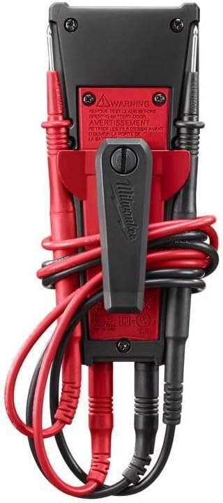
Figure 4: Rear view of the Milwaukee 2212-20, illustrating the integrated test lead storage and battery compartment.
7. Troubleshooting
| Problem | Possible Cause | Solution |
|---|---|---|
| Tester does not power on. | Dead or incorrectly installed batteries. | Check battery polarity; replace batteries. |
| No reading or incorrect reading. | Damaged test leads; open circuit; tester malfunction. | Inspect test leads for damage; ensure good contact with circuit; test on a known live circuit. If problem persists, contact support. |
| Continuity test fails on a known continuous circuit. | Damaged test leads; tester malfunction. | Inspect test leads for damage; ensure good contact. If problem persists, contact support. |
8. Specifications
- Model: 2212-20
- Brand: Milwaukee
- Measurement Type: Voltmeter
- Power Source: Battery Powered (2x AAA Alkaline)
- Item Weight: 12 ounces (approx. 340 grams)
- Dimensions (L x W x H): 7.5 x 5.5 x 1 inches (approx. 19.05 x 13.97 x 2.54 cm)
- Safety Rating: CAT IV 600V
- Included Components: Voltage Tester, Electrical Test Lead Set
9. Warranty and Support
Milwaukee products are designed for durability and reliability. For specific warranty information, please refer to the warranty card included with your product or visit the official Milwaukee website. For technical support or service inquiries, please contact Milwaukee customer service.
Contact information for support is typically found on the product packaging or the manufacturer's website.
Related Documents - 2212-20
 |
Milwaukee Auto Voltage/Continuity Tester Operator's Manual Operator's manual for the Milwaukee 2212-20 and 2213-20 Auto Voltage/Continuity Testers. Provides safety instructions, specifications, operation, maintenance, and warranty information for electrical testing. |
 |
Milwaukee Auto Voltage/Continuity Tester W/ Resistance 2213-20 Milwaukee Auto Voltage/Continuity Tester W/ Resistance (2213-20) offers accurate measurements, a backlit LCD, LED worklight, and auto-ranging for efficient electrical testing. Includes belt clip, test leads, batteries, and manual. |
 |
Milwaukee M18 Pipeline Inspection System Operator's Manual Official operator's manual for the Milwaukee M18 Pipeline Inspection System, covering setup, operation, safety, maintenance, and specifications for the Control Hub, Wireless Monitor, and Inspection Reels. |
 |
Milwaukee M18 FUEL Controlled Torque Impact Wrenches with TORQUE-SENSE Quick Start Guide Comprehensive quick start guide for Milwaukee M18 FUEL™ Controlled Torque Impact Wrenches featuring TORQUE-SENSE™ and ONE-KEY™ technology. Learn how to pair your tool with the mobile app, configure custom settings, perform training rundowns, and understand LED indicators for optimal performance and management. |
 |
Milwaukee M18 FUEL Grinder Operator's Manual This operator's manual provides essential safety instructions, operating procedures, maintenance guidelines, and specifications for Milwaukee M18 FUEL Braking Grinders, including models with ONE-KEY™ technology. |
 |
Milwaukee M18™ Cordless Impact Driver & Wrench Operator's Manual | Specs, Safety, Parts Comprehensive operator's manual for Milwaukee M18™ 1/4" Hex Impact Drivers (2656-20, 2657-20) and 3/8" & 1/2" Impact Wrenches (2658-20, 2659-20). Includes safety instructions, operating procedures, maintenance, specifications, and parts list. |
Ask a question about this manual
Ask about setup, troubleshooting, compatibility, parts, safety, or missing instructions. Manuals+ will review the question and use this page’s manual context to help answer it.