
1. Introduction
This manual provides essential information for the safe and efficient operation, maintenance, and troubleshooting of the Cincinnati Cost Breaker Hydraulic Press Brake, covering models 90, 135, 175, 230, and 350 CB Series. Adherence to the instructions outlined herein is crucial for ensuring operator safety, prolonging machine lifespan, and maintaining optimal performance. Operators must read and understand this manual completely before attempting to install, operate, or service the machine.
The Cincinnati Cost Breaker Hydraulic Press Brake is designed for precision bending of sheet metal and plate materials. Its robust construction and hydraulic system provide consistent and accurate bending capabilities for various industrial applications.
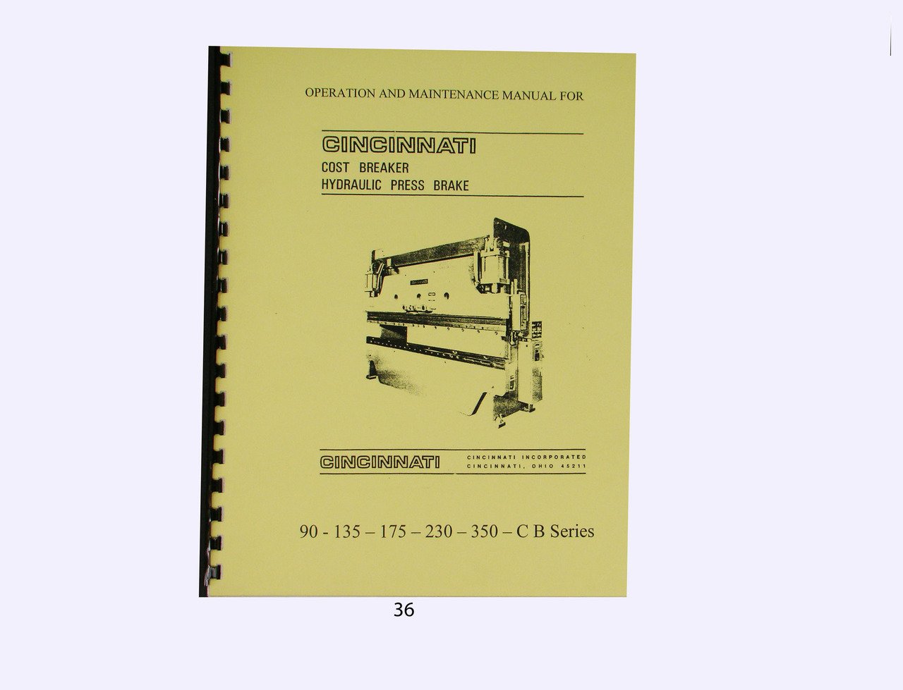
Figure 1: Cover of the Cincinnati Cost Breaker Hydraulic Press Brake Operation and Maintenance Manual. This image depicts the front cover of the instruction manual, indicating the series and models covered.
2. Safety Instructions
Operating a hydraulic press brake involves significant risks. Strict adherence to safety protocols is mandatory to prevent injury to personnel and damage to equipment. Always follow local safety regulations and company policies.
- Read the Manual: Ensure all operators have read and understood this entire manual before operating the machine.
- Personal Protective Equipment (PPE): Always wear appropriate PPE, including safety glasses, steel-toed boots, and hearing protection. Gloves should be worn when handling materials but removed when operating controls to prevent entanglement.
- Machine Guarding: Never operate the press brake with safety guards removed or bypassed. Regularly inspect guards for damage.
- Lockout/Tagout: Always follow Lockout/Tagout procedures before performing any maintenance, adjustments, or clearing jams.
- Work Area: Keep the work area clean, well-lit, and free from obstructions. Ensure adequate space around the machine for safe operation and material handling.
- Emergency Stop: Familiarize yourself with the location and operation of all emergency stop buttons. Test them regularly.
- Authorized Personnel: Only trained and authorized personnel should operate or maintain the press brake.
- Material Handling: Use proper lifting techniques and equipment when handling heavy or large materials.
3. Setup
Proper installation and setup are critical for the safe and accurate operation of the press brake. Consult the machine's foundation drawings for specific requirements.
- Foundation: Ensure the machine is installed on a level, stable concrete foundation capable of supporting its weight and dynamic loads.
- Leveling: Use precision levels to ensure the machine frame is perfectly level. Adjust leveling pads as necessary.
- Power Connection: Connect the machine to the appropriate electrical supply as specified on the machine's nameplate. Ensure proper grounding.
- Hydraulic Fluid: Fill the hydraulic reservoir with the recommended hydraulic fluid to the specified level. Refer to the machine's data plate for fluid type and capacity.
- Tooling Installation: Install the upper punch and lower die securely according to the bending application. Ensure tooling is clean, free of damage, and correctly aligned.
- Safety Device Checks: Verify that all safety devices, including light curtains, foot pedals, and emergency stops, are functioning correctly.
- Initial Test Run: Perform a no-load test run to check for smooth operation, proper ram movement, and absence of unusual noises.
4. Operating Instructions
This section outlines the general procedures for operating the Cincinnati Cost Breaker Hydraulic Press Brake. Specific bending operations may require additional steps or programming.
4.1 Pre-Operation Checks
- Inspect the machine for any visible damage or loose components.
- Check hydraulic fluid level and ensure no leaks are present.
- Verify tooling is correctly installed and secured.
- Clear the work area of any debris or unnecessary items.
- Ensure all safety guards are in place and functional.
4.2 Basic Operation Sequence
- Power On: Turn on the main power switch. The control panel should illuminate.
- Select Mode: Choose the desired operating mode (e.g., Manual, Jog, Automatic) from the control panel.
- Set Parameters: Input bending parameters such as bend angle, back gauge position, and ram speed into the control system.
- Material Placement: Carefully position the material on the lower die, ensuring it is flush against the back gauge.
- Initiate Bend: Activate the ram descent using the foot pedal or two-hand control. Maintain a safe distance from the bending area.
- Ram Return: The ram will automatically return to the top dead center after completing the bend, or it can be manually returned depending on the mode.
- Remove Part: Once the ram is fully retracted, safely remove the bent part.
4.3 Emergency Stop Procedure
In case of an emergency, immediately press any red emergency stop button. This will cut power to the machine's moving parts. To reset, twist or pull the button to release it, then follow the control panel's instructions to restart the machine.
5. Maintenance
Regular maintenance is essential for the longevity and reliable operation of your Cincinnati Cost Breaker Hydraulic Press Brake. Establish a routine maintenance schedule based on machine usage and environmental conditions.
5.1 Daily Checks
- Check hydraulic fluid level.
- Inspect tooling for wear or damage.
- Clean the work area and machine surfaces.
- Verify all safety devices are operational.
5.2 Weekly Checks
- Lubricate all grease points as indicated in the machine's lubrication chart.
- Inspect hydraulic hoses and fittings for leaks or damage.
- Check electrical connections for tightness and signs of overheating.
- Clean or replace air filters on the electrical cabinet.
5.3 Monthly/Quarterly Checks
- Check and adjust ram parallelism.
- Inspect and clean hydraulic oil filters. Replace if necessary.
- Verify back gauge accuracy and adjust if needed.
- Check for wear on guide ways and gibs; adjust or lubricate as required.
5.4 Hydraulic Fluid Replacement
Hydraulic fluid should be replaced annually or every 2000 operating hours, whichever comes first. Always use the manufacturer-recommended fluid type and dispose of old fluid responsibly.
6. Troubleshooting
This section provides solutions to common operational issues. For problems not listed here or for complex repairs, contact authorized service personnel.
| Problem | Possible Cause | Solution |
|---|---|---|
| Machine does not power on. | No main power supply; Emergency Stop engaged; Blown fuse/tripped breaker. | Check main power connection; Release Emergency Stop; Check and reset fuses/breakers. |
| Ram does not descend. | Low hydraulic fluid; Safety guard open; Foot pedal/two-hand control not activated; System pressure too low. | Check fluid level; Close safety guards; Activate controls correctly; Check hydraulic pressure settings. |
| Inaccurate bend angle. | Incorrect tooling; Worn tooling; Incorrect material properties entered; Ram parallelism off. | Verify correct tooling for material; Replace worn tooling; Re-enter material data; Adjust ram parallelism. |
| Excessive noise during operation. | Low hydraulic fluid; Air in hydraulic system; Worn pump; Loose components. | Check fluid level and top up; Bleed air from system; Inspect pump; Tighten loose components. |
Always ensure the machine is powered off and locked out before attempting any troubleshooting or repair procedures.
7. Specifications
The following specifications are typical for the Cincinnati Cost Breaker Hydraulic Press Brake CB Series. Specific values may vary by model (90, 135, 175, 230, 350) and configuration. Refer to your machine's data plate for exact specifications.
- Nominal Tonnage: 90 to 350 tons (depending on model)
- Overall Bending Length: Varies by model, typically 8 to 14 feet
- Distance Between Housings: Varies by model
- Throat Depth: Typically 8 to 12 inches
- Stroke Length: Typically 6 to 10 inches
- Open Height: Varies by model
- Motor Power: Varies by tonnage, typically 15 HP to 50 HP
- Hydraulic System Pressure: Up to 3000 PSI
- Electrical Requirements: 3-Phase, 208V/230V/460V, 60Hz (specifics on machine data plate)
8. Warranty and Support
Information regarding the warranty for your Cincinnati Cost Breaker Hydraulic Press Brake is typically provided at the time of purchase. Please refer to your original purchase documentation for specific warranty terms and conditions.
For technical support, spare parts, or service inquiries, please contact Cincinnati's authorized service department or your local distributor. When contacting support, please have your machine's model number and serial number readily available.
Contact Information:
Cincinnati Inc.
www.e-ci.com
(Note: This is a general contact link for the manufacturer. Specific support contacts may vary.)