1. Introduction
This manual provides essential information for the safe and efficient operation, installation, and maintenance of the Phoenix Contact ELR H5-IES-SC- 24DC/500AC-2 Motor Starter Unit. Please read this manual thoroughly before installation or operation and keep it for future reference.
2. Safety Instructions
Always observe the following safety precautions to prevent injury, damage to the device, or other property damage:
- Ensure all electrical work is performed by qualified personnel in accordance with local and national electrical codes.
- Disconnect power before performing any installation, maintenance, or troubleshooting.
- Do not operate the device if it is damaged or malfunctioning.
- Protect the device from moisture, dust, and extreme temperatures.
- Use only specified voltage and current ratings for connection.
3. Product Overview
The Phoenix Contact ELR H5-IES-SC- 24DC/500AC-2 is a motor starter unit designed for industrial electrical applications. It integrates functions for motor control and protection.
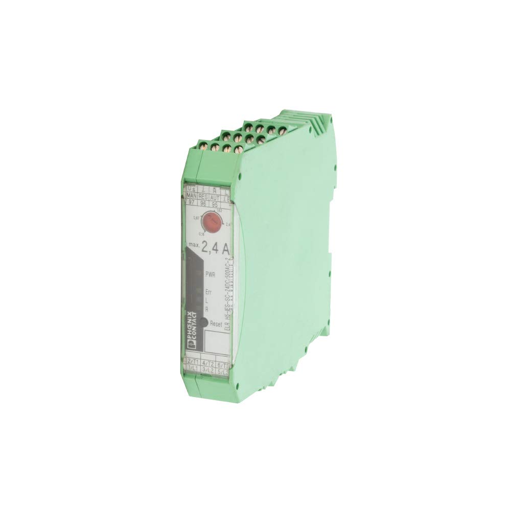
Figure 3.1: Front View of the Motor Starter Unit. This image displays the front panel of the Phoenix Contact ELR H5-IES-SC- 24DC/500AC-2. Visible features include the terminal block connections at the top and bottom, status indicators (PWR, Err, L, R), a reset button, and a dial for current adjustment (max. 2.4 A). The model number "ELR H5-IES-SC- 24DC/500AC-2" and "PHOENIX CONTACT" branding are also clearly visible.
4. Setup
Follow these steps for proper installation of the motor starter unit:
- Mounting: The unit supports screw mounting. Securely attach the device to a stable surface or DIN rail using appropriate screws. Ensure adequate ventilation around the unit.
- Wiring: Connect the power supply (24 VDC) to the designated terminals. Connect the motor leads to the output terminals (e.g., 2/T1, 4/T2, 6/T3 for output and 1/L1, 3/L2, 5/L3 for input). Refer to the wiring diagram on the unit for correct terminal assignments.
- Current Setting: Adjust the current limit dial on the front panel to the desired maximum operating current for your motor, up to 2.4 A.
- Initial Power-Up: After all connections are secure, apply power to the unit. Observe the PWR indicator for proper power-on status.
5. Operating Instructions
The motor starter unit is designed for straightforward operation:
- Power Indicator (PWR): A lit PWR indicator signifies that the unit is receiving power and is operational.
- Error Indicator (Err): If the Err indicator illuminates, it signifies a fault condition (e.g., overload, short circuit). Refer to the Troubleshooting section.
- Motor Direction Indicators (L/R): These indicators show the current direction of motor rotation (Left/Right), if applicable to your motor configuration and control scheme.
- Reset Button: After an error condition, press the "Reset" button to clear the fault and attempt to restart the motor.
- Current Adjustment: The dial labeled "max. 2,4 A" allows for fine-tuning the maximum permissible current for the connected motor. Ensure this is set appropriately to protect the motor.
6. Maintenance
The Phoenix Contact motor starter unit requires minimal maintenance. However, regular checks can ensure optimal performance and longevity:
- Cleaning: Periodically clean the exterior of the unit with a soft, dry cloth. Do not use abrasive cleaners or solvents. Ensure the unit is powered off before cleaning.
- Connection Checks: Annually inspect all electrical connections to ensure they are tight and free from corrosion. Loose connections can lead to overheating or intermittent operation.
- Ventilation: Ensure that the ventilation openings are not obstructed to prevent overheating.
7. Troubleshooting
If you encounter issues with your motor starter unit, refer to the following common problems and solutions:
| Problem | Possible Cause | Solution |
|---|---|---|
| Unit does not power on (PWR indicator off) | No power supply; incorrect wiring; faulty unit. | Check power source and connections. Verify input voltage (24 VDC). If problem persists, contact support. |
| Error (Err) indicator is lit | Motor overload; short circuit; motor locked rotor. | Disconnect power. Check motor and load for issues. Verify current setting. Press "Reset" button after resolving the fault. |
| Motor does not start or runs intermittently | Incorrect wiring; insufficient current setting; motor fault. | Verify all wiring connections. Ensure current setting is appropriate for the motor. Check motor for mechanical or electrical issues. |
8. Specifications
| Attribute | Value |
|---|---|
| Model Number | ELR H5-IES-SC- 24DC/500AC-2 |
| Manufacturer | Phoenix Contact |
| Brand | Generic |
| Voltage | 24 Volts (DC) |
| Max Current | 2.4 Amps (as indicated on unit) |
| Number Of Poles | 1 |
| Connector Type | Screw |
| Mounting Type | Screw Mount |
| Material | Plastic |
| Color | Green |
| Product Dimensions | 5 x 1 x 5 inches |
| Specification Met | RoHS |
| ASIN | B00MEJDGS8 |
| UPC | 755478219163 |
9. Warranty and Support
Specific warranty details for this product are not provided in the available information. For warranty claims or technical support, please contact the manufacturer, Phoenix Contact, or your authorized distributor. Keep your purchase receipt as proof of purchase.
For further assistance, refer to the official Phoenix Contact website or contact their customer service department.