1. Introduction
This manual provides essential information for the proper installation, operation, and maintenance of the Watt Stopper CX-105-3 Passive Infrared (PIR) Occupancy Sensor. Please read these instructions carefully before installation and retain this manual for future reference. The CX-105-3 is designed to detect occupancy in a given area and automatically control lighting or other electrical loads, contributing to energy efficiency.
2. Safety Information
WARNING: Risk of Electric Shock.
- Installation must be performed by a qualified electrician in accordance with all national and local electrical codes.
- Always disconnect power at the circuit breaker or fuse before installing or servicing the sensor.
- Ensure all wiring connections are secure and properly insulated.
- Do not install in wet or damp locations unless specifically rated for such environments.
3. Product Overview
The Watt Stopper CX-105-3 is a 24 VDC/VAC Passive Infrared Occupancy Sensor designed for ceiling or wall mount applications. It features a dual-element, temperature-regulated pyroelectric sensor for reliable motion detection and a two-sided aisleway lens for optimized coverage patterns.
Key Features:
- Power Requirement: Operates with a 24 VDC/VAC power pack (e.g., BZ-150, sold separately).
- Automatic On/Off: Provides automatic lighting control, with options for auto or manual-on when used with compatible power packs.
- Sensor Type: Dual Element, Temperature Regulated pyroelectric sensor for enhanced accuracy.
- Coverage: Offers 360-degree coverage, suitable for various room layouts.
- Adjustable Settings: User-adjustable time delay and sensitivity to customize performance.
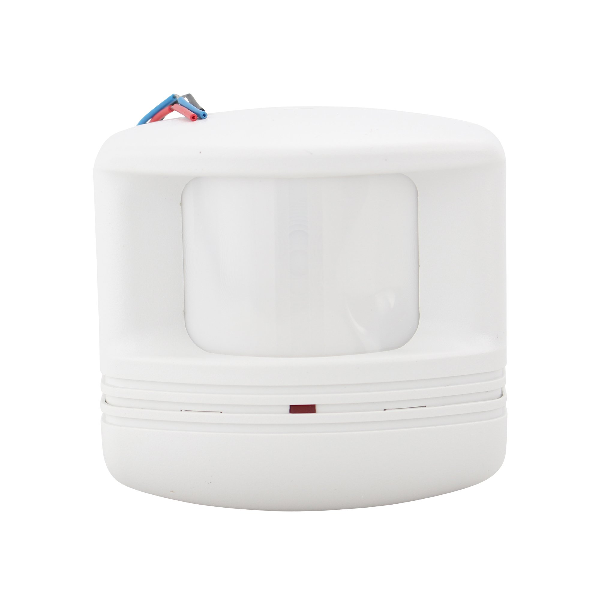
Figure 1: Watt Stopper CX-105-3 Passive Infrared Occupancy Sensor. This image shows the compact, white housing of the sensor, typically mounted on a ceiling or wall.
4. Installation
The CX-105-3 sensor is designed for either ceiling or wall mounting. Proper placement is crucial for optimal performance.
4.1 Pre-Installation Checks
- Ensure power is disconnected at the circuit breaker.
- Verify that a compatible 24 VDC/VAC power pack (e.g., Watt Stopper BZ-150) is available and correctly installed. The sensor requires this external power pack for operation.
- Choose a mounting location that provides an unobstructed view of the area to be monitored. Avoid placing the sensor near heat sources, air vents, or direct sunlight, which can cause false triggers.
4.2 Mounting
- Carefully remove the sensor cover to access the mounting holes and wiring terminals.
- Mount the sensor securely to the ceiling or wall using appropriate screws and anchors (not included). Ensure the sensor is level.
- Route the low-voltage wiring from the power pack to the sensor.
4.3 Wiring
Connect the sensor to the 24 VDC/VAC power pack according to the wiring diagram provided with the power pack. Typically, this involves connecting the sensor's low-voltage wires to the corresponding terminals on the power pack. Refer to the power pack's instruction manual for specific wiring details.
4.4 Post-Installation
- Replace the sensor cover, ensuring it is securely fastened.
- Restore power at the circuit breaker.
- Allow a brief warm-up period (typically 30-60 seconds) for the sensor to stabilize.
5. Operation
Once installed and powered, the CX-105-3 sensor will begin detecting motion within its 360-degree coverage area. When occupancy is detected, the sensor signals the connected power pack to activate the controlled load (e.g., turn on lights). When no motion is detected for a user-adjustable time delay, the sensor signals the power pack to deactivate the load.
5.1 Adjusting Settings
The CX-105-3 features user-adjustable settings for time delay and sensitivity. These adjustments are typically made via potentiometers or dip switches located on the sensor itself, often accessible by removing the sensor cover. Refer to the specific markings on your sensor for adjustment details.
- Time Delay: Sets the duration the load remains ON after the last detected motion. Adjust this to prevent lights from turning off too quickly in occupied spaces.
- Sensitivity: Determines how easily the sensor detects motion. Higher sensitivity detects smaller movements but may increase false triggers. Lower sensitivity requires more significant motion but reduces false triggers.
6. Maintenance
The Watt Stopper CX-105-3 sensor requires minimal maintenance to ensure continued optimal performance.
- Cleaning: Periodically wipe the sensor lens with a soft, dry cloth to remove dust or debris. Do not use abrasive cleaners or solvents, as these can damage the lens.
- Inspection: Occasionally inspect the sensor for any physical damage or loose connections.
No user-serviceable parts are inside the sensor. For any repairs, contact qualified service personnel.
7. Troubleshooting
If the sensor is not functioning as expected, review the following common issues and solutions:
| Problem | Possible Cause | Solution |
|---|---|---|
| Lights do not turn ON with motion. |
|
|
| Lights remain ON or turn ON without motion (false triggers). |
|
|
| Lights turn OFF too quickly. |
|
|
If problems persist after attempting these solutions, contact Watt Stopper technical support or a qualified electrician.
8. Specifications
| Attribute | Value |
|---|---|
| Model Number | CX-105-3 |
| Manufacturer | Wattstopper |
| Power Source | Wired Electric |
| Voltage | 24 Volts (VDC/VAC) |
| Mounting Type | Ceiling Mount, Wall Mount |
| Sensor Type | Passive Infrared (PIR), Dual Element, Temperature Regulated |
| Coverage | 360 Degree |
| Color | White |
| Item Weight | 1 pounds |
| Package Dimensions | 5.16 x 2.72 x 2.68 inches |
| Batteries Required | No |
9. Warranty and Support
For information regarding the product warranty, please refer to the documentation provided with your purchase or visit the official Watt Stopper website. For technical support, installation assistance, or troubleshooting beyond the scope of this manual, please contact Watt Stopper customer service directly.
Contact Information: Please refer to the manufacturer's official website or product packaging for the most current contact details.