Mastech MS2002A
MASTECH MS2002A Mini Autoranging Digital Clamp Meter User Manual
Model: MS2002A
1. Introduction
This manual provides essential information for the safe and effective operation of the MASTECH MS2002A Mini Autoranging Digital Clamp Meter. Please read this manual thoroughly before use and retain it for future reference.
The MS2002A is a compact and versatile digital clamp meter designed for measuring AC/DC voltage, AC current, and resistance. It features a 28mm (1.1 inch) jaw size, backlight, data hold function, and low battery indication.
2. Safety Information
Always adhere to basic safety precautions when using electrical testing equipment to reduce the risk of fire, electric shock, or personal injury.
- Ensure the meter is in good working condition before each use.
- Do not exceed the maximum input limits for any function.
- Use caution when working with voltages above 60V DC or 30V AC RMS, as they pose a shock hazard.
- Always disconnect power to the circuit under test before making connections or changing functions.
- Do not operate the meter if it appears damaged or if the test leads are damaged.
- Refer to the back of the device for important safety warnings, including instructions to remove test leads before opening the battery compartment.
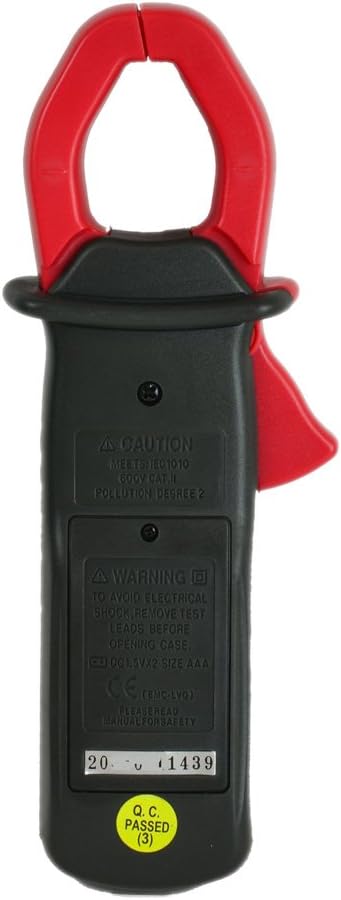
Image: Rear view of the MS2002A clamp meter, highlighting the battery compartment and printed safety warnings regarding electrical shock and battery replacement.
3. Product Features
The MASTECH MS2002A is equipped with several features for efficient and accurate measurements:
- Pocket Size Design: Compact and easy to carry.
- 200A Current and Voltage Check: Capable of measuring AC current up to 200A and AC/DC voltage.
- Backlight: Illuminates the LCD for clear readings in low-light conditions.
- Data Hold: Freezes the displayed reading for convenient recording.
- 3 1/2 Digits LCD: Provides a maximum reading of 1999.
- 2A Low Current Measurement: Allows for precise measurement of small AC currents.
- Low Battery Indication: Alerts the user when batteries need replacement.
- Jaw Size: 28mm (1.1 inch) for clamping around conductors.

Image: Angled view of the MS2002A clamp meter, showcasing its compact design, LCD display, function selector, and the current clamp jaw.
4. Setup
4.1. Battery Installation
The MS2002A requires 2 x 1.5V AAA batteries for operation.
- Ensure the meter is turned OFF.
- Locate the battery compartment on the back of the meter.
- Use a screwdriver to open the battery compartment cover.
- Insert two AAA batteries, observing the correct polarity (+ and -).
- Replace the battery compartment cover and secure it with the screw.
4.2. Initial Inspection
Before first use, inspect the meter for any signs of damage. Ensure the test leads (if included) are intact and free from cracks or frayed insulation.
5. Operating Instructions
Familiarize yourself with the meter's controls and display before taking measurements.

Image: Frontal view of the MS2002A clamp meter, clearly showing the LCD screen, rotary function switch, and buttons for AC/DC, Range, and Light.
5.1. Function Selection
Rotate the central dial to select the desired measurement function:
- OFF: Turns the meter off.
- A~: AC Current measurement.
- V~: AC Voltage measurement.
- V-: DC Voltage measurement.
- Ω: Resistance measurement.
- : Continuity test.
5.2. Button Functions
- HOLD: Press to freeze the current reading on the display. Press again to release.
- AC/DC: Toggles between AC and DC modes for voltage measurement if the dial position supports both.
- RANGE: Toggles between auto-ranging and manual ranging. In manual ranging, press to cycle through available ranges.
- LIGHT: Activates the display backlight for improved visibility.
5.3. Taking Measurements
5.3.1. AC Current Measurement (A~)
- Set the function dial to A~.
- Open the clamp jaw by pressing the trigger.
- Enclose only one conductor of the circuit within the clamp jaw. Ensure the jaw is fully closed.
- Read the AC current value on the display.
5.3.2. AC/DC Voltage Measurement (V~ / V-)
- Set the function dial to V~ for AC voltage or V- for DC voltage.
- Insert the red test lead into the VΩ input jack and the black test lead into the COM input jack.
- Connect the test leads in parallel to the circuit or component you wish to measure.
- Read the voltage value on the display.
5.3.3. Resistance Measurement (Ω)
- Set the function dial to Ω.
- Insert the red test lead into the VΩ input jack and the black test lead into the COM input jack.
- Ensure the circuit or component is de-energized before connecting the test leads.
- Connect the test leads across the component to measure its resistance.
- Read the resistance value on the display.
5.3.4. Continuity Test ()
- Set the function dial to the continuity symbol ().
- Insert the red test lead into the VΩ input jack and the black test lead into the COM input jack.
- Ensure the circuit or component is de-energized.
- Connect the test leads across the circuit or component.
- If the resistance is below approximately 50Ω, the meter will emit an audible beep, indicating continuity.
6. Maintenance
6.1. Cleaning
Wipe the meter's casing with a damp cloth and mild detergent. Do not use abrasives or solvents. Ensure the meter is dry before storage or use.
6.2. Battery Replacement
When the low battery indicator appears on the display, replace the batteries as described in Section 4.1. Prompt battery replacement ensures accurate readings and proper meter function.
6.3. Storage
If the meter is not used for an extended period, remove the batteries to prevent leakage and damage. Store the meter in a cool, dry place, away from direct sunlight and extreme temperatures.
7. Troubleshooting
| Problem | Possible Cause | Solution |
|---|---|---|
| Meter does not turn on. | Dead or incorrectly installed batteries. | Check battery polarity or replace batteries. |
| No reading or "OL" displayed. | Overload, open circuit, or incorrect function selected. | Ensure circuit is complete, select correct function, or check if measurement exceeds meter's range. |
| Inaccurate readings. | Low battery, damaged test leads, or external interference. | Replace batteries, inspect/replace test leads, or move away from strong electromagnetic fields. |
| Backlight not working. | Low battery or backlight button issue. | Replace batteries. If problem persists, contact support. |
8. Specifications
The following table outlines the key specifications for the MASTECH MS2002A Digital Clamp Meter:
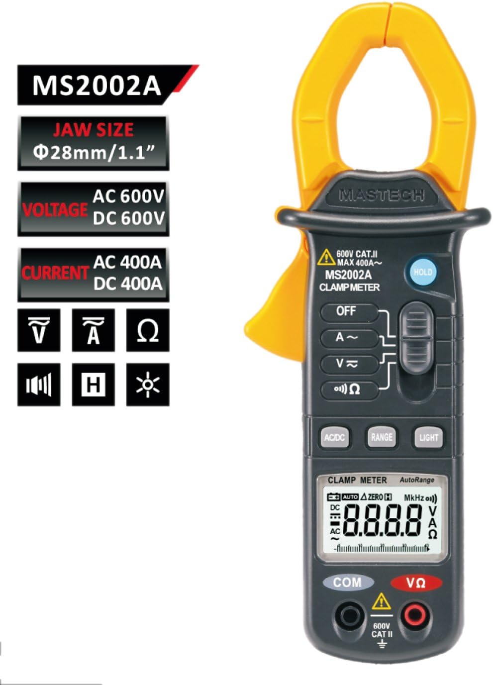
Image: A comprehensive table detailing the specifications of the MS2002A, including measurement ranges, accuracy, display type, jaw opening, continuity buzzer, data hold, display light, power supply, product size, product weight, and safety rating.
| Specification | Value |
|---|---|
| Model | MS2002A |
| Jaw Size | 28mm / 1.1 inch |
| Display | 3 1/2 digits LCD, Max reading 1999 |
| AC Current Range | 2A / 20A / 200A |
| AC Voltage Range | Up to 600V |
| DC Voltage Range | Up to 600V |
| Resistance Range | Up to 2000Ω |
| Power Source | 2 x 1.5V AAA Batteries |
| Item Weight | Approx. 4 ounces (113g) |
| Package Dimensions | 8.4 x 4.2 x 2.2 inches |
| Safety Rating | CAT II 600V |
9. Warranty and Support
For warranty information or technical support, please refer to the contact details provided with your purchase or visit the official Mastech website. Keep your purchase receipt as proof of purchase for warranty claims.
Note: Product specifications and features are subject to change without prior notice.
Related Documents - MS2002A
 |
MASTECH MS2016A Leakage Clamp Meter Operation Manual Comprehensive operation manual for the MASTECH MS2016A AC Leakage Clamp Meter, covering safety information, specifications, operating guidance, maintenance, and accessories. Features include AC/DC voltage, resistance, capacitance, continuity, diode, and temperature measurements. |
 |
MASTECH M9912 AC/DC Clamp Meter Quick Start Guide Quick start guide for the MASTECH M9912 AC/DC Clamp Meter, providing essential information on usage, specifications, and safety precautions. |
 |
Mastech MS2125A AC/DC Clamp Meter Quick Start Guide Quick start guide for the Mastech MS2125A AC/DC Clamp Meter, providing essential safety information, specifications, and operational instructions for electrical measurements. |
 |
MASTECH MY74 Digital Multimeter Quick Start Guide | Accurate Measurements Get started quickly with the MASTECH MY74 Digital Multimeter. This guide covers setup, safety, and specifications for accurate voltage, current, resistance, capacitance, frequency, and temperature measurements. |
 |
MASTECH MS2128 Digital Clamp Meter Quick Start Guide | AC/DC Voltage, Current, Resistance, Capacitance, Frequency Get started quickly with the MASTECH MS2128 Digital Clamp Meter. This guide covers safety, specifications, and basic operation for measuring voltage, current, resistance, capacitance, and frequency. |
 |
MASTECH MS2203 Three Phase Power Clamp Meter Quick Start Guide This document provides a quick start guide for the MASTECH MS2203 Three Phase Power Clamp Meter. It includes essential safety precautions, detailed specifications, and step-by-step instructions for measuring AC voltage, AC current, and single-phase/three-phase power. Learn how to use the meter for various electrical testing applications. |
Ask a question about this manual
Ask about setup, troubleshooting, compatibility, parts, safety, or missing instructions. Manuals+ will review the question and use this page’s manual context to help answer it.