1. Introduction
The HiLetgo MAX3232 RS232 to TTL Converter Module is designed to facilitate communication between RS232 serial devices and TTL (Transistor-Transistor Logic) level devices. This module is essential for integrating modern microcontrollers and other TTL-level components with traditional RS232 serial ports, which operate at different voltage levels.
It is commonly utilized in a variety of applications, including:
- Radio modification projects
- Mobile phone flashing and repair
- GPS system integration
- Automotive diagnostics and testing
- DVD player flashing
- Hard disk repair
- Set-top box upgrades
- General microcontroller programming and debugging

Figure 1: A pack of five HiLetgo MAX3232 RS232 to TTL Converter Modules, showing their compact size and standard DB9 connector.
2. Product Overview
Each module is built around the MAX3232 communication chip, ensuring reliable signal conversion. Key features include:
- Communication Chip: MAX3232
- Operating Voltage: 3.3V to 5V DC
- Working Current: Approximately 6mA
- Power Supply: Requires external power
- Interfaces: VCC (Power), GND (Ground), RXD (Receive Data), TXD (Transmit Data)
- Dimensions: 33mm x 32mm x 16mm (approximately)
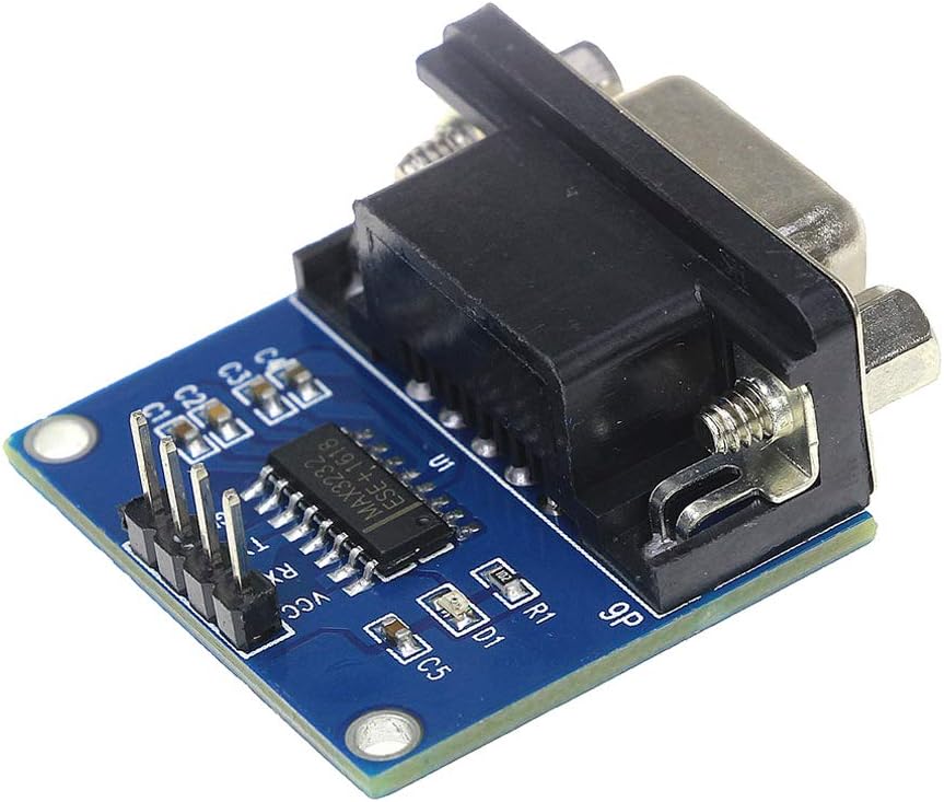
Figure 2: Detailed view of a single converter module, displaying the MAX3232 integrated circuit and the four primary connection pins: VCC (power), GND (ground), RX (receive), and TX (transmit).

Figure 3: This image shows the standard 9-pin D-sub (DB9) male connector, which provides the RS232 interface for the module.
3. Setup and Connection
Proper connection of the module is crucial for its functionality. The module features a DB9 male connector for the RS232 side and a 4-pin header for the TTL side.
3.1 Pinout Description
- VCC: Power supply input (3.3V to 5V DC).
- GND: Ground connection.
- RXD (TTL): Receive Data for the TTL side. This pin receives data from the RS232 device (via the module's internal conversion).
- TXD (TTL): Transmit Data for the TTL side. This pin transmits data to the RS232 device (via the module's internal conversion).
3.2 Important Note on TX/RX Labeling
It has been observed that the TXD and RXD labels on the module's PCB may be reversed relative to standard UART conventions. Typically, a UART's TX (transmit) connects to an adapter's RX (receive), and vice-versa. However, on this module, the labels often refer to the pin on the UART header you are connecting to. Therefore, for correct operation:
- Connect the TTL device's TXD pin to the module's pin labeled RXD.
- Connect the TTL device's RXD pin to the module's pin labeled TXD.
Always verify communication by testing the connections. If communication fails, try swapping the TXD and RXD connections on the TTL side.
3.3 Wiring Diagram Example
The following diagram illustrates a typical connection setup between the converter module and a microcontroller.

Figure 4: A schematic illustrating how to connect the converter module to a microcontroller (U1). It shows connections for 5V power, ground, and the RXD/TXD lines, along with external components like a crystal oscillator and capacitor. Note the connection of the module's RXD to the microcontroller's TXD, and the module's TXD to the microcontroller's RXD.
- Connect the module's VCC pin to your microcontroller's 3.3V or 5V power supply.
- Connect the module's GND pin to your microcontroller's Ground.
- Connect the module's RXD pin to your microcontroller's TXD pin.
- Connect the module's TXD pin to your microcontroller's RXD pin.
- Connect the DB9 connector to your RS232 device (e.g., computer serial port).
4. Operating Instructions
Once the module is correctly wired and powered, it acts as a transparent bridge between the RS232 and TTL serial communication protocols.
4.1 Power Indicator
The module includes a red LED that illuminates when power is supplied to the VCC and GND pins, indicating that the module is active.
4.2 Serial Communication Settings
For successful communication, ensure that the serial port settings on both the RS232 device (e.g., computer terminal software) and the TTL device (e.g., microcontroller) match. These settings typically include:
- Baud Rate: Common rates include 9600, 19200, 38400, 57600, 115200 bps.
- Data Bits: Usually 8 bits.
- Parity: None, Even, or Odd. Most commonly None.
- Stop Bits: 1 or 2 bits. Most commonly 1.
- Flow Control: None, Hardware (RTS/CTS), or Software (XON/XOFF). Most commonly None for simple applications.
Refer to the documentation of your RS232 and TTL devices for their specific serial communication requirements.
5. Maintenance
The HiLetgo MAX3232 RS232 to TTL Converter Module is a robust electronic component designed for durability. To ensure its longevity and reliable performance, follow these general maintenance guidelines:
- Handle with Care: Avoid dropping or subjecting the module to excessive physical shock.
- Environmental Protection: Keep the module in a dry environment, away from moisture, dust, and extreme temperatures.
- Static Discharge: Always handle the module with proper anti-static precautions to prevent damage to sensitive electronic components.
- Cleaning: If necessary, gently clean the module with a soft, dry cloth. Avoid using liquids or abrasive cleaners.
- Power Off Before Connecting: Always disconnect power from both the module and connected devices before making or changing any wiring connections.
6. Troubleshooting
If you encounter issues while using the converter module, consider the following troubleshooting steps:
- No Power Indicator LED:
- Verify that VCC and GND are correctly connected to a 3.3V-5V DC power source.
- Ensure the power supply is active and providing the correct voltage.
- No Communication:
- Check TX/RX Connections: As noted in Section 3.2, the TXD/RXD labels on the module might be reversed relative to standard UART conventions. Try swapping the connections between the module's RXD/TXD pins and your TTL device's TXD/RXD pins.
- Verify Serial Settings: Ensure that the baud rate, data bits, parity, and stop bits are identical on both the RS232 and TTL sides.
- Ground Connection: Confirm that both the module and the connected TTL device share a common ground.
- Voltage Levels: Ensure your TTL device's logic levels are compatible with the module's operating voltage (3.3V-5V).
- Cable Integrity: Check all wiring for loose connections or damage.
- Intermittent Communication:
- Ensure stable power supply.
- Check for electromagnetic interference (EMI) if operating in a noisy environment.
- Verify cable lengths are not excessive for the chosen baud rate.
7. Specifications
| Feature | Specification |
|---|---|
| Brand | HiLetgo |
| Model Number | 3-01-0136 |
| Communication Chip | MAX3232 |
| Operating Voltage | 3.3V - 5V DC |
| Working Current | 6mA (typical) |
| Power Supply | External |
| Interface Pins | VCC, GND, RXD, TXD |
| RS232 Connector | DB9 Male |
| Dimensions (L x W x H) | 33mm x 32mm x 16mm (approx.) |
| Compatible Devices | Microcontrollers, Cellular Phones, GPS, DVD Players, Video Game Consoles (e.g., Xbox 360 for specific applications) |
8. Warranty Information
Specific warranty details for this product are not provided in the available documentation. For information regarding product warranty, please contact HiLetgo customer support directly.
9. Technical Support
For technical assistance, troubleshooting guidance, or any inquiries regarding the HiLetgo MAX3232 RS232 to TTL Converter Module, please contact our support team:
- Email: support@hiletgo.com
- Website: www.hiletgo.com

Figure 5: Examples of product packaging, including a sealed plastic bag and a small cardboard box, both branded with 'HiLetgo' and providing contact details for technical support: support@hiletgo.com.