Dieffematic THALIA
BFT THALIA Control Unit Instruction Manual
Model: THALIA | Brand: Dieffematic
1. Introduction
This manual provides essential information for the proper installation, operation, and maintenance of the BFT THALIA control unit. This unit is designed to replace or serve as a central control board for gate automation systems, ensuring reliable and efficient performance. Please read this manual carefully before proceeding with any installation or operation.
2. Safety Information
Important Safety Instructions:
- Installation and maintenance must be performed by qualified personnel only, in compliance with local electrical and safety regulations.
- Disconnect the main power supply before performing any work on the control unit or connected components.
- Ensure proper grounding of the system.
- Do not expose the control unit to moisture, rain, or extreme temperatures.
- Use only original spare parts and accessories recommended by the manufacturer.
3. Package Contents
The package typically includes:
- 1 x BFT THALIA Control Unit
- Instruction Manual (this document)
- Mounting accessories (screws, plugs - may vary)
4. Setup and Installation
Proper installation is crucial for the safe and correct functioning of the BFT THALIA control unit. Refer to the wiring diagrams provided with your specific gate automation system for detailed connections.
4.1 Mounting the Control Unit
Mount the control unit in a protected, dry, and easily accessible location, away from direct sunlight and sources of vibration. Ensure the enclosure is securely fastened to a stable surface using appropriate mounting hardware.
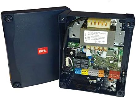
Figure 1: The BFT THALIA control unit with its protective cover open, revealing the internal circuit board, transformer, and various terminal blocks for electrical connections. The BFT logo is visible on the closed part of the casing.
4.2 Electrical Connections
Before making any connections, ensure the main power supply is disconnected. Connect the following:
- Main Power Supply: Connect the 230V AC power supply to the designated terminals (L, N, PE).
- Motor Connections: Connect the gate motor wires to the motor output terminals.
- Safety Devices: Connect photocells, safety edges, and other safety devices to their respective inputs.
- Command Devices: Connect push buttons, key switches, remote control receivers, and other command devices.
- Accessories: Connect flashing lights, courtesy lights, and other accessories as required.
Refer to the detailed wiring diagram specific to your gate system and the THALIA unit for precise terminal assignments.
4.3 Initial Power-Up and Configuration
Once all connections are secure, restore the main power supply. The unit may require initial programming or auto-learning procedures depending on the specific gate system and desired functionalities. Consult the gate system's manual for programming steps, such as setting limits, operating modes, and remote control pairing.
5. Operating Instructions
The BFT THALIA control unit manages the operation of your automated gate system. Operation is typically initiated via external command devices:
- Remote Control: Pressing the designated button on a paired remote control will activate the gate (open/close/stop cycle).
- Key Switch/Push Button: Activating an external key switch or push button connected to the unit will initiate the gate movement.
- Automatic Closing: If configured, the gate will automatically close after a set pause time, provided no safety devices are activated.
Always ensure the gate path is clear before and during operation.
6. Maintenance
Regular maintenance ensures the longevity and safe operation of your gate system and the THALIA control unit. Always disconnect power before performing any maintenance.
- Visual Inspection: Periodically check for any visible damage to the unit, wiring, or connections.
- Cleanliness: Keep the control unit enclosure clean and free from dust, debris, and insects.
- Terminal Tightness: Ensure all electrical terminals are securely tightened.
- Safety Devices: Regularly test all connected safety devices (photocells, safety edges) to ensure they are functioning correctly.
For complex issues or internal component checks, contact a qualified technician.
7. Troubleshooting
If the gate system or control unit is not functioning as expected, consider the following common issues:
- No Power:
- Check the main power supply and circuit breaker.
- Ensure all power connections to the THALIA unit are secure.
- Gate Not Moving:
- Check if safety devices (photocells) are obstructed or misaligned.
- Verify that remote controls or command devices are functioning and paired.
- Inspect motor connections.
- Erratic Operation:
- Check for loose wiring connections.
- Ensure there are no interferences affecting remote control signals.
For persistent problems, consult a qualified technician or the manufacturer's support.
8. Specifications
| Feature | Detail |
|---|---|
| Product Model | THALIA |
| Brand | Dieffematic |
| ASIN | B00LLF3Z46 |
| Manufacturer Reference | 221429087040 |
| First Available Date on Amazon.it | September 20, 2018 |
| Typical Application | Gate Automation Control Unit |
9. Warranty and Support
For warranty information, technical support, or service requests, please contact the product seller or the manufacturer, Dieffematic. Keep your purchase receipt as proof of purchase.
For further assistance, you may refer to the official BFT documentation or contact their authorized service centers.