1. Introduction
Thank you for choosing the UNITECK UNISOLAR 20.24 DR Solar Charge Controller. This device is designed to manage the power flow from your solar panels to your battery bank, ensuring efficient charging and protecting your batteries from overcharge and deep discharge. It is suitable for 12V and 24V solar systems, automatically detecting the system voltage. This manual provides essential information for the safe and effective installation, operation, and maintenance of your solar charge controller.
2. Safety Instructions
Please read all instructions and warnings carefully before installation and operation. Failure to follow these instructions may result in electric shock, fire, or serious injury.
- Ensure all connections are tight and correct to avoid excessive heat buildup.
- Always connect the battery to the charge controller first, then the solar panel, and finally the load. Disconnect in the reverse order.
- Do not attempt to repair or modify the controller. Refer all servicing to qualified personnel.
- Install the controller in a well-ventilated area, away from flammable gases and liquids.
- Wear eye protection when working with batteries.
- Ensure the solar panel's open-circuit voltage (Voc) does not exceed the controller's maximum input voltage.
3. Product Overview
The UNISOLAR 20.24 DR is a robust solar charge controller featuring an LCD display for easy monitoring of system parameters. It is designed to efficiently manage your solar power system.
Key Features:
- Automatic 12V/24V system voltage detection.
- LCD display for real-time system status.
- Multiple battery charging stages (Bulk, Absorption, Float).
- Protection against overcharge, over-discharge, reverse polarity, and short circuit.
- Load control function.
Components:
The controller typically includes terminals for connecting solar panels, batteries, and DC loads. An integrated LCD screen provides operational feedback.
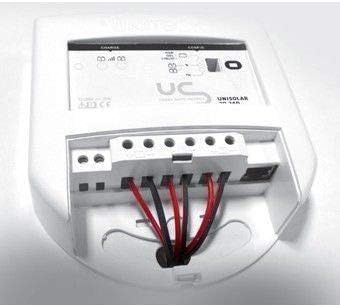
Figure 1: Rear view of the UNITECK UNISOLAR 20.24 DR solar charge controller showing wiring terminals. This image displays the rear of the UNITECK UNISOLAR 20.24 DR solar charge controller, highlighting the connection terminals for the solar panel, battery, and load. Wires are shown connected to these terminals, illustrating a typical installation setup.
4. Setup and Installation
Follow these steps carefully to install your UNISOLAR 20.24 DR charge controller.
- Mounting: Choose a dry, well-ventilated location, protected from direct sunlight and moisture. Mount the controller vertically on a non-flammable surface, ensuring adequate airflow around the unit.
- Wire Preparation: Use appropriate wire gauges for your system's current and distance. Strip approximately 8-10mm of insulation from the wire ends.
- Battery Connection: Connect the battery wires to the battery terminals on the controller (marked with a battery symbol). Ensure correct polarity: positive to positive (+), negative to negative (-). This is the first connection to make.
- Solar Panel Connection: Connect the solar panel wires to the solar panel terminals on the controller (marked with a solar panel symbol). Ensure correct polarity.
- Load Connection (Optional): If using the controller's load output, connect your DC load wires to the load terminals (marked with a light bulb symbol). Ensure correct polarity.
- Verify Connections: Double-check all connections for tightness and correct polarity before proceeding.
5. Operating Instructions
Once installed, the UNISOLAR 20.24 DR will automatically begin operating. The LCD display provides real-time information about your system.
LCD Display Information:
- Battery Voltage: Displays the current voltage of your battery bank.
- Charging Current: Shows the current flowing from the solar panels to the battery.
- Load Current: Indicates the current being drawn by the connected DC loads.
- Battery State of Charge (SOC): Often represented by a battery icon with varying fill levels.
- System Status Icons: Icons may indicate solar charging, load on/off, and fault conditions.
Load Control:
The controller may feature a button or menu option to manually turn the DC load output on or off. Consult the on-screen prompts or specific product documentation for detailed load control settings, such as timer functions.
6. Maintenance
Regular maintenance ensures optimal performance and longevity of your solar charge controller.
- Check Connections: Periodically inspect all wiring connections for tightness and corrosion. Loose connections can cause overheating and damage.
- Clean the Controller: Keep the controller clean and free of dust. Use a dry cloth to wipe the casing. Do not use liquids or solvents.
- Inspect Wiring: Check for any signs of wear, fraying, or damage to the insulation of all cables connected to the controller.
- Ventilation: Ensure the area around the controller remains clear for proper ventilation.
7. Troubleshooting
If you encounter issues with your UNISOLAR 20.24 DR, refer to the following common problems and solutions.
| Problem | Possible Cause | Solution |
|---|---|---|
| No display/Controller not working | Battery not connected or low voltage; reverse polarity. | Check battery connections and voltage. Ensure correct polarity. Charge battery if critically low. |
| Battery not charging | Solar panel not connected; low sunlight; faulty solar panel; open circuit in wiring. | Check solar panel connections and polarity. Verify sunlight conditions. Test solar panel voltage. Inspect wiring for breaks. |
| Load not working | Load output off; over-discharge protection active; faulty load. | Check if load output is enabled via controller settings. Ensure battery voltage is above the low voltage disconnect threshold. Test the load directly. |
| Overcharging indication | Controller malfunction. | Disconnect solar panels and battery. Reconnect battery first, then solar panels. If issue persists, contact support. |
If the problem persists after attempting these solutions, please contact UNITECK customer support.
8. Specifications
| Feature | Detail |
|---|---|
| Brand | UNITECK |
| Model | UNISOLAR 20.24 DR |
| System Voltage | 12V / 24V Auto-detection (Implied by model name '20.24') |
| Max. Charge Current | 20A (Implied by model name '20.24') |
| Display Type | LCD |
| Material | Plastic |
| ASIN | B00KY7347U |
| Country of Origin | France |
9. Warranty and Support
For warranty information and technical support, please refer to the warranty card included with your product or visit the official UNITECK website. Keep your purchase receipt as proof of purchase for any warranty claims.