1. Introduction
This manual provides instructions for the safe and effective operation of the Mastech MS2108A Auto Range DC AC Current Digital Clamp Meter Multimeter. This instrument is designed for measuring AC/DC voltage and current, resistance, capacitance, frequency, duty cycle, diode, and continuity. It features an auto-ranging function, LCD backlight, clamp lighting, and data hold capabilities, making it suitable for various electrical testing applications.
2. Safety Information
Warning: To avoid electrical shock or personal injury, read all safety information before using this product. Use the product only as specified in this manual, or the protection provided by the product may be impaired.
- Always ensure the meter is in the correct function and range before making measurements.
- Do not apply more than the rated voltage, as marked on the meter, between the terminals or between any terminal and earth ground.
- Use caution when working with voltages above 30V AC RMS, 42V peak, or 60V DC. These voltages pose a shock hazard.
- Before measuring current, ensure the circuit is de-energized and the clamp jaws are properly closed around the conductor.
- Do not operate the meter with the battery cover open.
- Replace the battery immediately when the low battery indicator appears.
- Always disconnect test leads from the circuit before changing functions.
- Adhere to all local and national safety codes.
3. Product Overview and Features
The Mastech MS2108A is a versatile digital clamp meter designed for electrical professionals and enthusiasts. Its key features include:
- AC/DC voltage and current measurement
- Resistance, capacitance, frequency, and duty cycle measurement
- Diode and continuity test functions
- Clamp for non-contact AC/DC current measurement
- LCD with backlight and bar graph display
- Integrated clamp lighting bulb
- Relative value measurement
- Auto-ranging function
- Data hold, maximum (MAX), and minimum (MIN) value measuring
- Automatic power off and low battery indication
- Full overload protection and dual insulation
- Durable over-molding rubber case for shake-proof and skid-proof handling
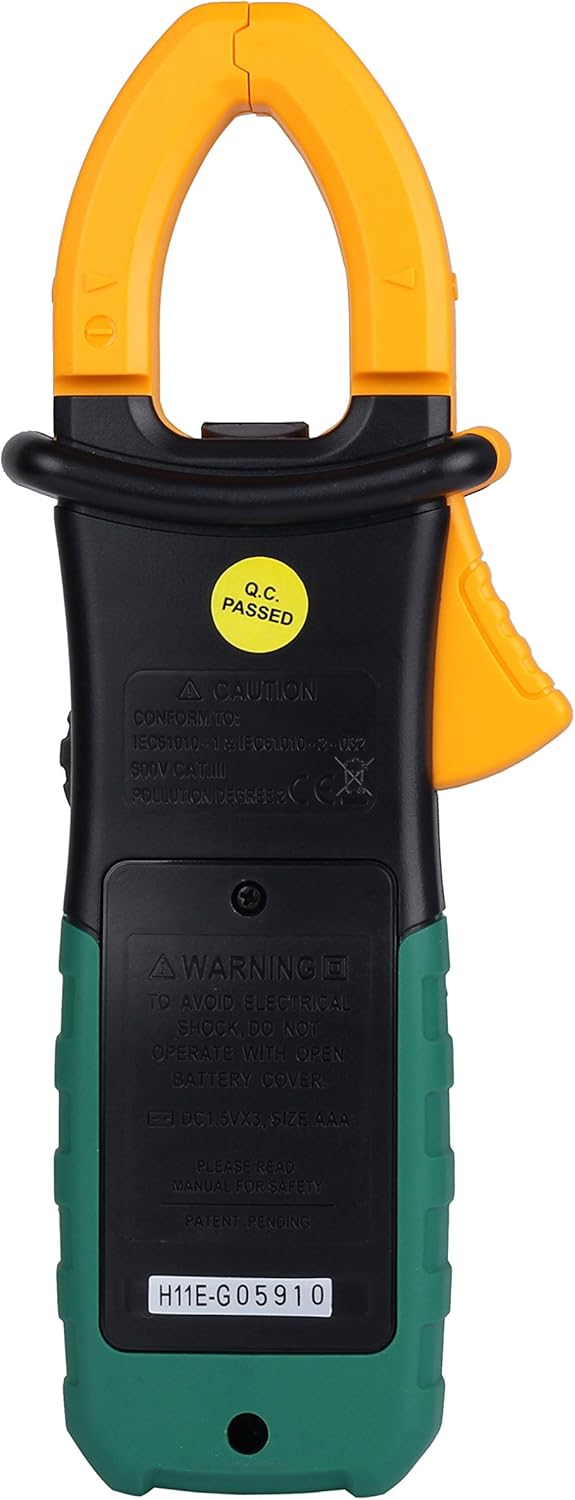
Figure 3.1: Front view of the Mastech MS2108A Digital Clamp Meter, showing the display, function dial, and clamp jaws.
4. Package Contents
Verify that all items are present and in good condition upon opening the package:
- Mastech MS2108A Digital Clamp Meter
- Test Leads (one red, one black)
- Carrying Case
- User Manual (this document)

Figure 4.1: The Mastech MS2108A Clamp Meter, test leads, and carrying case.
5. Setup
5.1 Battery Installation
- Ensure the meter is turned OFF.
- Locate the battery compartment cover on the back of the meter.
- Use a screwdriver to loosen the screw(s) securing the battery cover.
- Remove the battery cover.
- Insert three AAA 1.5V batteries, observing the correct polarity (+ and -).
- Replace the battery cover and tighten the screw(s).
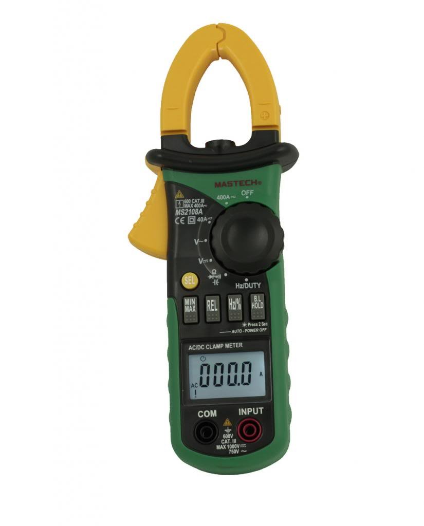
Figure 5.1: Rear view of the clamp meter, indicating the battery compartment location.
5.2 Connecting Test Leads
For voltage, resistance, capacitance, frequency, duty cycle, diode, and continuity measurements:
- Insert the red test lead into the "INPUT" terminal.
- Insert the black test lead into the "COM" (common) terminal.
6. Operating Instructions
6.1 Power On/Off
Rotate the function dial from the "OFF" position to any desired measurement function to turn the meter ON. To turn OFF, rotate the dial back to the "OFF" position.
6.2 Function Selection
The large rotary dial allows selection of various measurement functions. Some positions on the dial may have multiple functions (e.g., AC voltage and DC voltage). Press the "SEL" button to cycle through these functions.

Figure 6.1: Side view of the clamp meter, highlighting the function dial and control buttons.
6.3 AC/DC Current Measurement (Clamp)
- Rotate the function dial to the "A~" (AC Current) or "A=" (DC Current) position.
- Press the clamp trigger to open the jaws.
- Enclose a single conductor (not a power cord with multiple wires) within the clamp jaws. Ensure the jaws are fully closed.
- Read the current value on the LCD.
- For DC current, observe the polarity indicated on the display.

Figure 6.2: The clamp jaws of the meter, showing the integrated work light for illuminating the measurement area.
6.4 AC/DC Voltage Measurement
- Connect the red test lead to the "INPUT" terminal and the black test lead to the "COM" terminal.
- Rotate the function dial to the "V~" (AC Voltage) or "V=" (DC Voltage) position. Use the "SEL" button if needed.
- Connect the test leads in parallel to the circuit or component under test.
- Read the voltage value on the LCD.
6.5 Resistance, Capacitance, Frequency, Duty Cycle, Diode, and Continuity
For these measurements, connect the test leads as described in Section 5.2. Rotate the function dial to the appropriate position and use the "SEL" button to select the specific function if multiple are available on one dial position.
- Resistance (Ω): Ensure the circuit is de-energized before measuring resistance.
- Capacitance (F): Discharge capacitors before measurement.
- Frequency (Hz) / Duty Cycle (%): Connect across the signal source.
- Diode Test (→|): Connect the red lead to the anode and black lead to the cathode.
- Continuity Test ()))): A built-in buzzer will sound if the resistance is below approximately 50Ω.
6.6 Special Functions
- "HOLD" Button: Press to freeze the current reading on the display. Press again to release.
- "MAX/MIN" Button: Press to enter MAX/MIN recording mode. The meter will display the maximum or minimum value measured since entering the mode. Press again to cycle between MAX, MIN, and current reading. Hold to exit.
- "REL" (Relative) Button: Press to store the current reading as a reference value. Subsequent measurements will be displayed as the difference from this reference. Press again to exit.
- Backlight/Clamp Light: The backlight and clamp light can be activated for improved visibility in low-light conditions. Refer to the specific button on the meter (often combined with another function or a dedicated light button).
7. Maintenance
7.1 Cleaning
Wipe the case with a damp cloth and mild detergent. Do not use abrasives or solvents. Keep the terminals free of dirt and moisture.
7.2 Battery Replacement
When the low battery indicator appears on the display, replace the batteries as described in Section 5.1. Always use three new AAA 1.5V batteries.
7.3 Storage
If the meter is not used for an extended period, remove the batteries to prevent leakage and damage. Store the meter in its carrying case in a cool, dry place.
8. Troubleshooting
| Problem | Possible Cause | Solution |
|---|---|---|
| Meter does not power on. | Dead or incorrectly installed batteries. | Check battery polarity; replace batteries. |
| "OL" (Overload) displayed. | Input exceeds selected range or meter's maximum capacity. | Select a higher range (if manual ranging) or ensure input is within meter's specifications. |
| Inaccurate readings. | Poor test lead connection, incorrect function selected, or external interference. | Ensure leads are firmly connected; verify function selection; move away from strong electromagnetic fields. |
| No continuity beep. | Circuit resistance is too high. | Check the circuit for breaks or high resistance points. |
9. Specifications
The following are general specifications for the Mastech MS2108A. Detailed ranges and accuracies can be found in the full technical datasheet.
- Brand: Mastech
- Model Number: MS2108A
- Measurement Type: Multimeter, Clamp Meter
- Power Source: Battery Powered (3 x AAA 1.5V)
- Included Components: Case, Test Leads
- Safety Rating: IEC 61010-1, CAT III 600V
- Display: LCD with Backlight and Bar Graph
- Auto Power Off: Yes
- Data Hold: Yes
- MAX/MIN Measurement: Yes
- Relative Measurement: Yes
10. Warranty and Support
Mastech products are manufactured to high quality standards. For warranty information and technical support, please refer to the warranty card included with your purchase or contact your local Mastech distributor. Keep your purchase receipt as proof of purchase.