1. General Description
This manual provides comprehensive instructions and maintenance procedures for Ingersoll Rand Type 30, 20, and 25 horsepower compressors. It covers various models including T3025LTM, T3025HTM, T3025LBP, T3025HBP, 20T, 20S, 20S2, 20S3, 20S4, and 25T. The document, originally published in August 1973 as Form 1084-F (superseding 1084-E), details general descriptions, accessories, piping arrangements, installation, regulation, operation, troubleshooting, and maintenance. This booklet covers both single and two-stage compressors. While single and two-stage machines operate somewhat differently, the basic principle of operation of each is treated separately in the following paragraphs.
For maintaining the air receiver, or system, air pressure within predetermined limits, the compressor is equipped with one of three types of regulation. The type of regulation used depends upon the compressor's application. Starting unloading, or the discharge of air from the cylinders when the unit stops so that it is unloaded when started, is accomplished by the action of the centrifugal unloader operating a pilot valve, which in turn activates the air head unloaders, thus relieving pressure.

Figure 1-1: Internal Construction of Typical 20 and 25 H.P. Compressor. This diagram illustrates the key internal components of the compressor, including the air head, manifold, safety valve, piston, connecting rod, intercooler, centrifugal unloader, frame, pilot valve, cylinder relief valve, and low oil level switch. Understanding these components is crucial for proper operation and maintenance.
2. Safety Information
Always prioritize safety when operating or maintaining the compressor. Read and understand all instructions before use. Failure to follow safety guidelines can result in serious injury or equipment damage.
- Ensure the compressor is installed in a well-ventilated area.
- Always disconnect power before performing any maintenance or service.
- Do not operate the compressor if any parts are damaged or missing.
- Wear appropriate personal protective equipment (PPE), including eye and hearing protection.
- Regularly inspect safety valves and pressure relief devices to ensure proper function.
3. Installation
3.1 Location & Foundation
Proper location and a stable foundation are critical for efficient and safe compressor operation. Ensure the compressor is placed on a level, solid surface capable of supporting its weight and resisting vibration.
3.2 Installing Belts or Aligning Couplings
Follow manufacturer guidelines for installing drive belts or aligning couplings. Incorrect installation can lead to premature wear, reduced efficiency, and potential equipment failure. Ensure proper tension for belts and precise alignment for couplings.
3.3 Inlet and Discharge Air Piping
Install inlet and discharge air piping according to local codes and best practices. Use appropriate pipe sizes and materials to minimize pressure drop and ensure safe operation. Ensure all connections are secure and leak-free.
4. Setup
4.1 Accessories & Piping Arrangement
Refer to the specific diagrams and instructions for your compressor model regarding the arrangement of accessories and piping. This includes components such as aftercoolers, automatic water valves, and automatic drain traps. Proper setup ensures optimal performance and longevity of the system.
- Air-Cooled Aftercoolers: Connect as per diagram to reduce air temperature.
- Water-Cooled Aftercoolers: Ensure proper water supply and drainage connections.
- Accessory Piping: Follow specified routes and secure all connections.
- Automatic Water Valve: Install to manage condensate.
- Automatic Drain Trap: Ensure correct orientation and function for condensate removal.
5. Operation
5.1 Regulation
The compressor's regulation system controls air pressure. Understand the type of regulation installed on your unit (e.g., constant speed control, dual control) and how to adjust it for desired pressure settings. Refer to Form 1084-F for detailed regulation procedures.
5.2 Starting Procedures
Before starting, ensure all safety checks are complete. Verify oil levels, check for obstructions, and confirm all valves are in the correct position. Follow the specific starting sequence for your model, which may involve manual or automatic controls.
5.3 Important Operation Notes
Pay attention to operational indicators such as pressure gauges, temperature readings, and unusual noises. Promptly address any deviations from normal operating parameters to prevent damage or failure.
6. Maintenance
Regular maintenance is essential for the longevity and efficient operation of your Ingersoll Rand compressor. Adhere to the recommended service schedule.
6.1 Routine Inspection & Service
Perform daily or weekly inspections including checking oil levels, draining condensate, and inspecting belts for wear. Refer to the manual for detailed inspection checklists.
6.2 Compressor Lubrication
Use only recommended lubricants. Check and change compressor oil at specified intervals. Proper lubrication prevents excessive wear on moving parts.
6.3 Motor Lubrication & Care
Follow the motor manufacturer's guidelines for lubrication and general care. Keep motor vents clear of dust and debris to ensure adequate cooling.
6.4 Component Replacement
- Piston Pin Removal & Replacement: Follow precise steps to avoid damage.
- Crankshaft Bearing Replacement: Requires specialized tools and expertise.
- Oil Seal Replacement: Ensure correct seal type and proper installation to prevent leaks.
6.5 Precautions for Extended Shutdown
If the compressor will be out of service for an extended period, follow specific procedures for draining fluids, protecting internal components, and storing the unit to prevent corrosion and damage.
7. Troubleshooting
7.1 Trouble Chart
Consult the trouble chart provided in the original manual (page 24) for common issues and their solutions. This chart helps diagnose problems such as insufficient pressure, excessive noise, or overheating.
| Problem | Possible Cause | Solution |
|---|---|---|
| Compressor will not start | No power, motor overload, low voltage | Check power supply, reset breaker, verify voltage |
| Low air pressure | Air leak, worn piston rings, clogged air filter | Inspect for leaks, replace rings, clean/replace filter |
| Excessive noise | Loose parts, worn bearings, improper lubrication | Tighten fasteners, replace bearings, check oil level |
8. Specifications
This manual provides technical data relevant to the Ingersoll Rand Type 30, 20 & 25 HP compressors.
- Original Publication Date: August 1973
- Manual Form Number: 1084-F (Supersedes 1084-E)
- Print Length: 35 pages
- Language: English
- Covered Models: T3025LTM, T3025HTM, T3025LBP, T3025HBP, 20T, 20S, 20S2, 20S3, 20S4, 25T
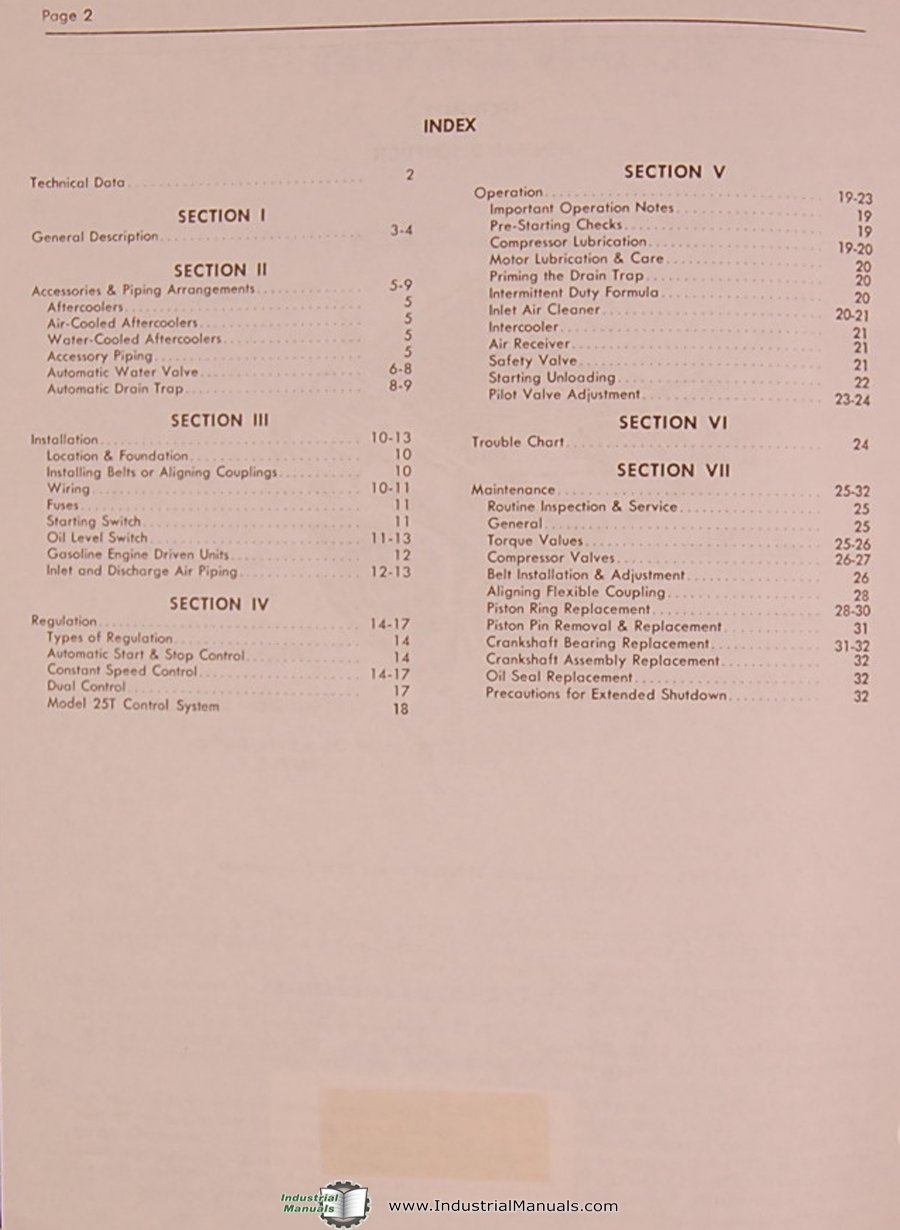
Figure 8-1: Index Page from the Original Manual. This image displays the detailed index from the 1973 manual, outlining sections such as Technical Data, General Description, Accessories & Piping Arrangements, Installation, Regulation, Operation, Trouble Chart, and Maintenance, along with their respective page numbers.