
Introduction
The ASTATIC PDC1 is a compact analog SWR/RF test meter designed to assess the condition of 50-ohm antennas and coaxial cables for CB radio operations. It features switches for 10 watts and 100 watts, and forward/reverse power measurement capabilities, operating within a frequency range of 27MHz. This manual provides detailed instructions for its proper setup, operation, and maintenance.
Product Overview
Key Features
- 3-function analog meter
- Indicates the condition of 50-ohm antennas and coax for CB operation
- Tests for SWR (Standing Wave Ratio) or relative power
- 10-watt and 100-watt power range switches
- Frequency Range: 27MHz
Components
The ASTATIC PDC1 meter includes an analog display for SWR and power readings, along with various switches and connectors for operation. A Workman black 3-foot jumper cable is also included for convenient connection.
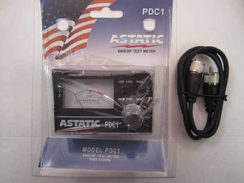
This image displays the ASTATIC PDC1 SWR/RF Test Meter, a compact black unit with an analog meter face. To its right, a Workman 3-foot jumper cable with PL259 connectors is visible, ready for connection. The meter features switches for power range and measurement mode.
Setup
Connecting the Meter
- Connect your CB radio's antenna output to the "TX" (Transmitter) connector on the back of the ASTATIC PDC1 meter using a suitable coaxial cable.
- Connect your antenna or a dummy load to the "ANT" (Antenna) connector on the back of the ASTATIC PDC1 meter using the provided Workman 3-foot jumper cable or another appropriate coaxial cable.
- The meter is designed to operate without external power for basic SWR and power measurements. However, for meter illumination, connect a DC 5-12V power supply to the small power socket on the back.
Operating Instructions
Understanding the Display
- The analog meter features three sets of numbers. The top two rows indicate power readings (Watts), with the upper row for the 100W range and the lower row for the 10W range.
- The third set of numbers, labeled "SWR", indicates the Standing Wave Ratio. The green zone signifies an acceptable SWR, while the red zone indicates poor SWR, suggesting an antenna mismatch.
Power Measurement
- Ensure the meter is correctly connected between your radio and a dummy load.
- Set the right-side switch to the desired power range: "10W" for lower power or "100W" for higher power.
- Set the middle switch to "WATT" to measure power.
- Set the left-side switch to "FW" (Forward Power) to measure the power transmitted from your radio.
- Key your microphone and observe the needle on the meter to read the forward power output.
- To measure reflected power, set the left-side switch to "RW" (Reverse Power), key your microphone, and observe the needle.
SWR Measurement
Calibration
- Ensure the meter is correctly connected between your radio and your antenna.
- Set the right-side switch to the appropriate power range ("10W" or "100W") based on your radio's output.
- Set the middle switch to "SWR".
- Set the left-side switch to "CAL" (Calibration).
- Key your microphone and, while transmitting, slowly turn the "CAL" knob on the right side until the meter needle points to the "CAL" mark at the far right of the red SWR zone. This calibrates the meter for your current power output.
- Release the microphone.
Reading SWR
- After calibration, set the left-side switch to "SWR".
- Key your microphone again and observe the needle. The reading on the "SWR" scale indicates your antenna's Standing Wave Ratio.
- Aim for an SWR reading in the green zone (typically below 2.0) for optimal antenna performance and to prevent damage to your radio.
Maintenance
- Cleaning: Use a soft, dry cloth to clean the meter's exterior. Avoid abrasive cleaners or solvents.
- Storage: Store the meter in a cool, dry place away from direct sunlight and extreme temperatures.
- Protection: When not in use, ensure all connections are covered to prevent dust and moisture ingress.
- Handling: Handle the meter with care to avoid dropping or physical impact, which could affect its calibration and functionality.
Troubleshooting
High SWR Readings
- Check Antenna: Ensure your antenna is correctly assembled, mounted, and tuned for the operating frequency (27MHz for CB).
- Inspect Coaxial Cable: Look for kinks, damage, or loose connections in the coaxial cable between the radio, meter, and antenna. A faulty cable can cause high SWR.
- Verify Connections: Confirm all connectors (PL259) are securely tightened.
- Grounding: Ensure your antenna system has a proper ground.
No Power or SWR Reading
- Check Radio Output: Verify your CB radio is transmitting power.
- Meter Connections: Double-check all cable connections to the meter's TX and ANT ports.
- Switch Settings: Ensure the power range and measurement mode switches are set correctly for the desired measurement.
Specifications
| Feature | Specification |
|---|---|
| Model Number | PDC1 |
| Frequency Range | 27MHz |
| Max Power Handling | 100 Watts |
| Impedance | 50 Ohm |
| Meter Type | 3-Function Analog |
| Power for Illumination | DC 5-12V (optional) |
| Product Dimensions | 4 x 4 x 4 inches |
| Item Weight | 12 ounces |
Warranty and Support
For warranty information and technical support, please refer to the documentation provided with your purchase or contact Astatic customer service. Keep your proof of purchase for any warranty claims.


