1. Introduction
This manual provides essential instructions for the installation, operation, and maintenance of the BFT Elba BU Control Unit, model D113717 00002. This unit is designed for controlling gate automation systems, ensuring reliable and safe operation. Please read this manual carefully before proceeding with any installation or operation. Keep this manual for future reference.
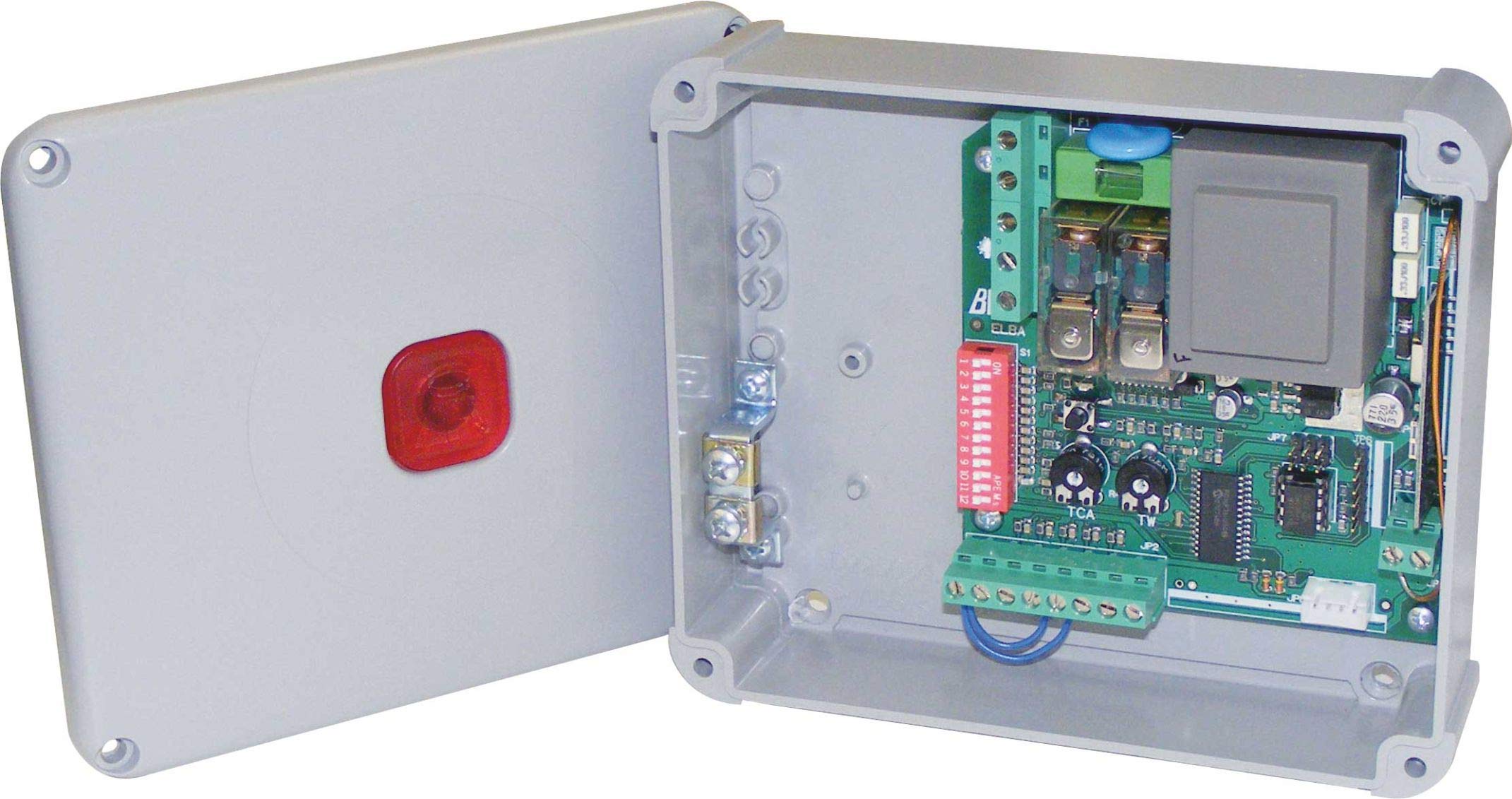
Figure 1: BFT Elba BU Control Unit D113717 00002. This image shows the main control board with various terminals and components.
2. Safety Information
WARNING: Incorrect installation or improper use can cause serious injury or damage.
- All installation and maintenance work must be performed by qualified personnel only.
- Disconnect power before performing any work on the control unit.
- Ensure all electrical connections comply with local and national electrical codes.
- Do not expose the unit to moisture, rain, or extreme temperatures.
- Use only original BFT spare parts and accessories.
- Keep children and unauthorized persons away from the gate automation system during operation.
3. Package Contents
Verify that all components are present and undamaged upon unpacking:
- BFT Elba BU Control Unit (Model D113717 00002)
- Instruction Manual (this document)
- Mounting hardware (screws, anchors - may vary)
- Wiring terminals (pre-installed or separate - may vary)
4. Setup and Installation
This section outlines the general steps for installing the control unit. Refer to detailed wiring diagrams provided with the product for specific connections.
- Mounting: Securely mount the control unit in a protective enclosure, away from direct weather exposure and vibrations. Ensure adequate ventilation.
- Power Connection: Connect the main power supply (230V AC, 50 Hz) to the designated terminals. Ensure proper grounding.
- Motor Connections: Connect the gate motor(s) to the appropriate output terminals on the control unit.
- Accessory Connections: Connect safety devices (e.g., photocells, safety edges), command devices (e.g., push buttons, key switches), and other accessories (e.g., flashing lights) to their respective terminals.
- Antenna Connection: If using a radio receiver, connect the antenna to improve signal reception.
- Initial Power-Up: After all connections are verified, apply power to the unit. Observe any indicator lights for initial status.
5. Operating Instructions
The BFT Elba BU Control Unit offers various functionalities for gate automation.
- Programming: The unit typically features a programming interface (e.g., dip switches, push buttons, or a display) to set operating parameters such as opening/closing times, force, pause times, and safety logic. Refer to the detailed programming guide for your specific gate system.
- Manual Operation: In case of power failure or emergency, the gate can usually be disengaged for manual operation. Consult your gate motor's manual for instructions on manual release.
- Remote Control: If a radio receiver is connected, remote controls can be programmed to operate the gate. Follow the instructions for pairing remote controls with the receiver.
6. Maintenance
Regular maintenance ensures the longevity and safe operation of your BFT Elba BU Control Unit and the entire gate automation system.
- Annual Inspection: Have a qualified technician inspect the control unit and all associated components annually.
- Cleanliness: Keep the control unit enclosure clean and free from dust, insects, and debris.
- Wiring Check: Periodically check all wiring connections for tightness and signs of wear or corrosion.
- Safety Devices: Regularly test all safety devices (photocells, safety edges) to ensure they are functioning correctly.
- Power Disconnection: Always disconnect the main power supply before performing any cleaning or inspection inside the control unit.
7. Troubleshooting
Before contacting technical support, review the following common issues and their potential solutions.
| Problem | Possible Cause | Solution |
|---|---|---|
| Gate does not respond to commands. | No power, remote control battery flat, safety device activated, faulty wiring. | Check power supply, replace remote battery, check safety devices for obstructions, inspect wiring connections. |
| Gate opens but does not close. | Safety device (e.g., photocell) obstructed or misaligned, programming error. | Clear obstruction from safety devices, clean photocell lenses, realign photocells, check programming parameters. |
| Gate operates intermittently. | Loose wiring connection, interference with remote signal, motor issue. | Check all wiring connections, ensure antenna is properly connected, consult a technician for motor diagnosis. |
If the problem persists after attempting these solutions, contact a qualified BFT service technician.
8. Specifications
| Feature | Detail |
|---|---|
| Model Number | D113717 00002 |
| Brand | BFT |
| Input Voltage | 230 V AC |
| Frequency | 50 Hz |
| Manufacturer | B.F.T. SRL |
| Compatible Devices | Gate automation systems (e.g., gate motors, safety sensors) |
9. Warranty and Support
For detailed warranty information, please refer to the official warranty documentation provided with your product or visit the official BFT website.
For technical support, spare parts, or service, please contact your authorized BFT dealer or a qualified service technician. Ensure you have your product model number (D113717 00002) and purchase details available when seeking support.
Important: Any unauthorized repairs or modifications will void the product warranty.