1. Introduction
The Mastech MS2002 is a versatile manual range AC clamp meter designed for accurate electrical measurements. It is capable of measuring AC/DC voltage, AC current, resistance, and performing continuity tests. This manual provides detailed instructions for the safe and effective use of your device.
2. Safety Information
Always read and understand all safety warnings and operating instructions before using this instrument. Failure to observe safety precautions could result in electric shock, injury, or damage to the meter.
- Do not apply more than the rated voltage, as marked on the meter, between the terminals or between any terminal and earth ground.
- Use extreme caution when working with voltages above 60V DC or 30V AC RMS. Such voltages pose a shock hazard.
- Before opening the case to replace the battery or fuses, always disconnect the test leads from any live circuits and remove them from the meter's input terminals.
- Inspect the test leads for damaged insulation or exposed metal. Replace if damaged.
- Ensure the function switch is in the correct position for the desired measurement before connecting to the circuit.
- This meter is rated for CAT II 600V. Adhere to these ratings for safe operation.
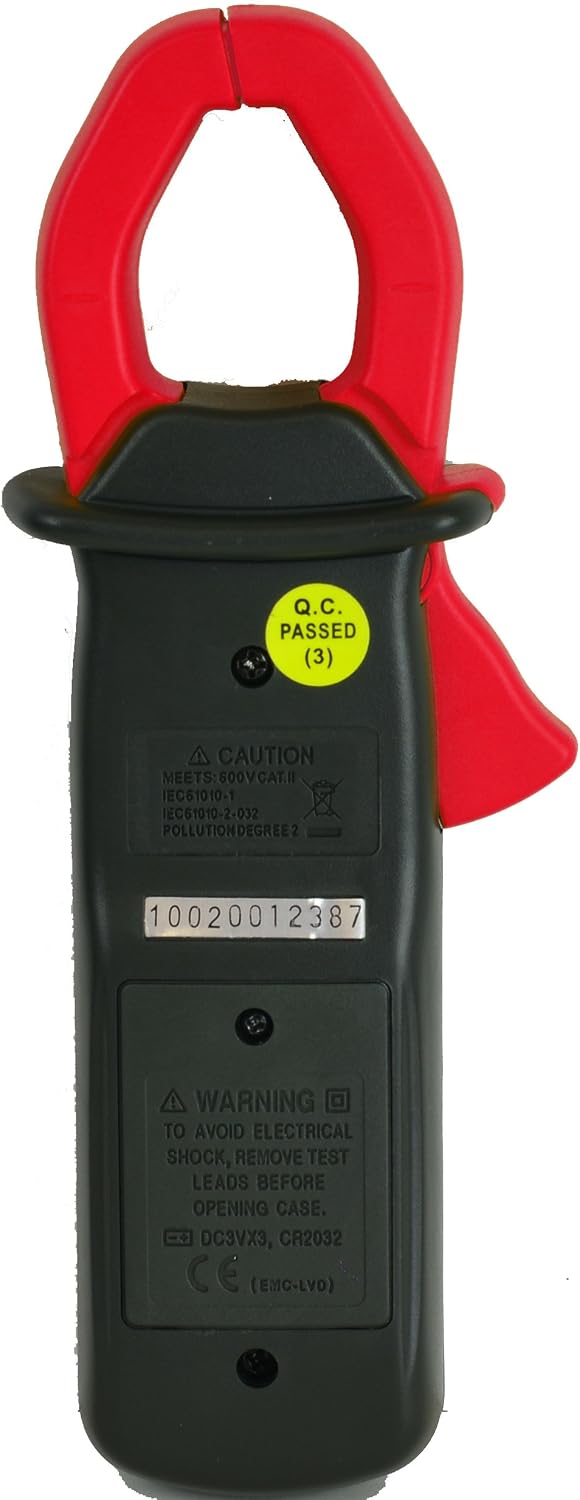
Figure 2.1: Back view of the MS2002, highlighting safety warnings and battery compartment.
3. Package Contents
Upon opening the package, please verify that all items listed below are present and in good condition:
- Sinometer MS2002 Clamp Meter (1 unit)
- Test Leads (1 pair)
- User Manual (1 copy)
- Carrying Pouch (1 unit)
- 9V Battery (1 unit, typically pre-installed)
- Lanyard (1 unit)

Figure 3.1: Contents included with the MS2002 Clamp Meter.
4. Product Overview
Familiarize yourself with the components of your Mastech MS2002 Clamp Meter:

Figure 4.1: Front view of the MS2002 Clamp Meter.
- Current Clamp: Used for non-contact measurement of AC current.
- Function Dial: Rotary switch to select measurement functions (ACA, ACV, DCV, Resistance, Continuity).
- LCD Display: Digital readout for measurements, units, and indicators. Features a backlight for low-light conditions.
- HOLD Button: Freezes the current reading on the display. Press again to release.
- LIGHT Button: Activates or deactivates the LCD backlight.
- ON/OFF Button: Powers the meter on or off.
- COM Input Jack: Common (negative) input terminal for test leads.
- VΩ Input Jack: Positive input terminal for voltage, resistance, and continuity measurements.
5. Setup
5.1 Battery Installation
The MS2002 uses one 9V battery. The battery is typically pre-installed. If replacement is needed:
- Ensure the meter is turned OFF and disconnect all test leads from the meter and any circuits.
- Locate the battery compartment cover on the back of the meter (refer to Figure 2.1).
- Unscrew the retaining screw(s) and remove the cover.
- Carefully remove the old battery (if present) and connect the new 9V battery, observing correct polarity.
- Replace the battery compartment cover and secure it with the screw(s).
5.2 Connecting Test Leads
For voltage, resistance, and continuity measurements, connect the test leads as follows:
- Insert the black test lead into the COM (common) input jack.
- Insert the red test lead into the VΩ (voltage/resistance/continuity) input jack.
6. Operating Instructions
6.1 Power On/Off
Press the ON/OFF button to turn the meter on. Press it again to turn the meter off.
6.2 AC Current Measurement (ACA)
- Turn the function dial to the desired AC current range (20A or 200A).
- Open the current clamp by pressing the trigger.
- Enclose only one conductor of the circuit within the clamp jaws. Ensure the jaws are fully closed.
- Read the AC current value on the LCD display.
6.3 AC/DC Voltage Measurement (ACV/DCV)
- Connect the test leads as described in Section 5.2.
- Turn the function dial to the V~ (AC Voltage) or V- (DC Voltage) position. The meter has a 600V range for both.
- Connect the test leads in parallel to the circuit or component you wish to measure.
- Read the voltage value on the LCD display.
6.4 Resistance Measurement (Ω)
- Connect the test leads as described in Section 5.2.
- Turn the function dial to the Ω (Resistance) position. The meter has a 2kΩ range.
- Ensure the circuit or component under test is de-energized before connecting the test leads.
- Connect the test leads across the component.
- Read the resistance value on the LCD display.
6.5 Continuity Test ())))
- Connect the test leads as described in Section 5.2.
- Turn the function dial to the ))) (Continuity) position.
- Ensure the circuit or component under test is de-energized.
- Connect the test leads across the component.
- If the resistance is below approximately 50Ω, the buzzer will sound, indicating continuity. The resistance value will also be displayed.
6.6 Data Hold
Press the HOLD button to freeze the current reading on the LCD display. This is useful for taking measurements in hard-to-reach areas. Press the HOLD button again to release the reading and return to live measurement mode.
6.7 Backlight
Press the LIGHT button to turn the LCD backlight on or off. The backlight improves visibility in dimly lit environments.
7. Maintenance
7.1 Cleaning
To clean the meter, wipe the case with a damp cloth and a mild detergent. Do not use abrasives or solvents. Ensure the meter is completely dry before use.
7.2 Battery Replacement
When the battery symbol appears on the LCD display, the battery voltage is low and needs to be replaced. Refer to Section 5.1 for detailed battery replacement instructions.
7.3 Storage
When not in use, store the meter in its carrying pouch in a dry, cool environment, away from direct sunlight and extreme temperatures. If storing for extended periods, it is advisable to remove the battery to prevent leakage.
8. Troubleshooting
| Problem | Possible Cause | Solution |
|---|---|---|
| Meter does not power on. | Dead or improperly installed battery. | Check battery polarity or replace the 9V battery. |
| "OL" (Overload) displayed. | Input value exceeds the selected range. | Select a higher range or verify the measurement is within the meter's capabilities. |
| Inaccurate readings. | Incorrect function selected; poor test lead connection; external interference. | Ensure the function dial is set correctly. Check test lead connections. Move away from strong electromagnetic fields. |
| No continuity buzzer sound. | Circuit resistance is too high; test leads not making good contact. | Ensure the circuit is de-energized. Check test lead connections. The buzzer typically sounds for resistance below 50Ω. |
9. Specifications
| Parameter | Specification |
|---|---|
| Display | 1999 Counts LCD with Backlight |
| DC Voltage (DCV) | 600V ± 1% |
| AC Voltage (ACV) | 600V ± 1.5% |
| AC Current (ACA) | 20A ± 2.0%, 200A ± 1.5% (Max 200A for this model) |
| Resistance | 2kΩ ± 1% |
| Continuity Test | Audible buzzer (approx. <50Ω) |
| Max. Conductor Diameter | Φ28 mm |
| Dimensions | 194 x 72 x 35 mm |
| Weight | Approx. 200g (including battery) |
| Power Source | 9V Battery |
| Features | Data Hold, Back-lit Display |
| Safety Rating | CAT II 600V |
10. Warranty and Support
The Mastech MS2002 Clamp Meter comes with a 30-day money-back guarantee and a 1-year limited warranty from the date of purchase. This warranty covers defects in materials and workmanship under normal use.
For warranty claims, technical support, or any questions regarding the operation of your device, please contact your retailer or the manufacturer's customer service. Please have your purchase receipt and product model number (MS2002) available when contacting support.