Introduction
This instruction manual provides essential information for the safe and effective installation, operation, and maintenance of your LiftMaster Garage Door Opener 41AS050-1 Receiver Logic Board. Please read all instructions carefully before proceeding with installation or use. Retain this manual for future reference.
Important Safety Information
- Always disconnect power to the garage door opener unit before attempting any installation, repair, or maintenance. Failure to do so may result in electric shock or serious injury.
- Ensure all wiring is performed by a qualified individual and complies with local electrical codes.
- Keep hands and clothing clear of moving parts of the garage door and opener.
- This logic board is designed for specific LiftMaster garage door opener models. Verify compatibility before installation.
Setup and Installation
The 41AS050-1 Receiver Logic Board is a replacement component for compatible LiftMaster garage door openers. Installation typically involves replacing the existing logic board within the opener unit.
Required Tools:
- Small Phillips head screwdriver
- Small flathead screwdriver
- Wire strippers (if new wiring is required)
Installation Steps:
- Disconnect Power: Unplug the garage door opener from the electrical outlet or turn off the circuit breaker supplying power to the unit.
- Access the Logic Board: Carefully open the housing of your garage door opener. This usually involves removing a few screws from the front or sides of the unit.
- Disconnect Wires: Note the position and connection of all wires attached to the existing logic board. It is recommended to take a photograph for reference. Disconnect all wires, including those for safety sensors, wall control, and power.
- Remove Old Board: Unscrew and remove the old logic board from its mounting points.
- Install New Board: Position the new LiftMaster 41AS050-1 Receiver Logic Board in place and secure it with the screws.
- Reconnect Wires: Reconnect all wires to the new logic board, ensuring they are placed in their correct terminals as noted in step 3. Ensure wires are stripped to the appropriate length (approximately 7/16" or 11mm) for secure connections.
- Close Housing: Carefully close and secure the garage door opener housing.
- Restore Power: Plug the garage door opener back into the electrical outlet or turn on the circuit breaker.
- Test and Program: Proceed to the programming section to program your remote controls and ensure proper operation.
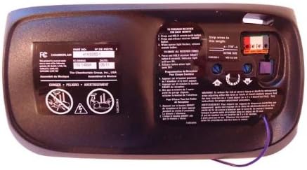
Image: Back of the LiftMaster 41AS050-1 Receiver Logic Board. This view displays the part number (41AS050-1), FCC compliance information, and detailed instructions for programming new remote controls and erasing all existing remote codes. Key elements include wire terminals for connection and a "SMART" button for programming.
Programming Remote Controls:
After installation, you will need to program your remote controls to the new logic board. Refer to the instructions on the back of the unit or your remote control's manual.
- To Program a New Remote:
- Press and release the "SMART" button on the logic board. The indicator light will turn on.
- Within 30 seconds, press and hold the button on your remote control that you wish to operate the garage door.
- Release the remote button when the opener lights flash or two clicks are heard. The remote is now programmed.
- To Erase All Remote Controls:
- Press and hold the "SMART" button on the logic board until the indicator light turns off (approximately 6 seconds).
- All previously programmed remote controls are now erased. You will need to reprogram any remotes you wish to use.
Operating Your Garage Door Opener
Once the 41AS050-1 Receiver Logic Board is installed and your remote controls are programmed, your garage door opener should function as intended. Pressing the programmed button on your remote control or the wall control unit will activate the garage door.
- Ensure the path of the garage door is clear before operation.
- Test safety reversal features regularly as per your garage door opener's main manual.
Maintenance
The LiftMaster 41AS050-1 Receiver Logic Board itself requires no specific routine maintenance. However, regular maintenance of your overall garage door opener system is crucial for longevity and safe operation.
- Refer to your primary garage door opener manual for recommended maintenance schedules and procedures.
- Periodically check all wiring connections to the logic board to ensure they are secure.
- Keep the garage door opener unit clean and free from dust and debris.
Troubleshooting
If your garage door opener is not functioning correctly after installing the new logic board, consider the following:
- No Response from Remote:
- Ensure the remote control has fresh batteries.
- Verify that the remote control has been correctly programmed to the new logic board (refer to "Programming Remote Controls" section).
- Check for interference from other radio frequency devices.
- Garage Door Not Moving:
- Confirm that the garage door opener unit is receiving power. Check the power outlet and circuit breaker.
- Inspect all wiring connections to the logic board for looseness or damage.
- Check the safety sensors. If they are misaligned or obstructed, the door may not close.
- If the issue persists, consult your primary garage door opener manual for further troubleshooting steps or contact a qualified technician.
- Intermittent Operation:
- This could indicate a loose wire connection or potential interference. Recheck wiring and consider potential sources of interference.
Specifications
| Manufacturer | LiftMaster |
| Part Number | 41AS050-1 |
| Item Model Number | TRTAZ11A |
| Item Weight | 0.01 ounces |
| Package Dimensions | 10.91 x 6.97 x 3.31 inches |
| Batteries Required? | No |
| ASIN | B00E3KVLLK |
| Date First Available | April 22, 2014 |
Warranty Information
Specific warranty details for the LiftMaster 41AS050-1 Receiver Logic Board are not provided in this manual. Please refer to the warranty documentation included with your purchase or contact the seller or LiftMaster directly for current warranty terms and conditions.
Customer Support
For technical assistance, replacement parts, or further inquiries regarding your LiftMaster 41AS050-1 Receiver Logic Board, please contact LiftMaster customer support or the authorized dealer from whom you purchased the product. You may find contact information on the official LiftMaster website or your purchase receipt.