1. Introduction
This manual provides essential information for the safe and effective operation, maintenance, and troubleshooting of the Fluke 28IIEX/ETL Intrinsically Safe True-RMS Digital Multimeter. This device is engineered for precise electrical measurements in potentially hazardous environments, offering robust performance and advanced safety features.
2. Safety Information
WARNING: Read and understand all safety information before using this product. Failure to do so may result in serious injury or death.
2.1 General Safety Guidelines
- Always use the multimeter with the specified test leads and accessories.
- Do not use the multimeter if it appears damaged or is operating abnormally.
- Observe all local and national safety codes.
- Ensure the correct function and range are selected before making measurements.
- Avoid working alone in hazardous environments.
2.2 Intrinsically Safe Operation
The Fluke 28IIEX/ETL is designed for use in hazardous locations classified as:
- ATEX: II 2 G Ex ia IIC T4 Gb, II 2 D Ex ia IIIC T130°C Db, I M1 Ex ia I Ma
- NEC-500: Class I, Div 1, Groups A-D, 130 °C
- IEXEx: Ex ia IIC T4 Gb, Ex ia IIIC T130°C Db, Ex ia I Ma
These ratings ensure the device will not ignite explosive atmospheres under normal or fault conditions. Always ensure the device is used within its specified environmental and electrical limits for intrinsically safe operation.
2.3 Electrical Safety Ratings
The multimeter meets International Electrotechnical Commission (IEC) safety standard 61010 and is certified for:
- Category III 1000V: For measurements on building circuit installations (e.g., service panel parts, branch circuits, fixed installations).
- Category IV 600V: For measurements at the origin of the installation (e.g., electricity meters, primary over-current protection equipment).
- Pollution Degree 2: For indoor use.
2.4 Environmental Protection
The device is Ingress Protection (IP) certified IP67, meaning it is waterproof, dust-proof, and drop-proof, suitable for harsh industrial environments.
3. Product Overview
The Fluke 28IIEX/ETL is a robust digital multimeter designed for reliability and accuracy. It features a large LCD display with a two-level bright white backlight for visibility in various lighting conditions.
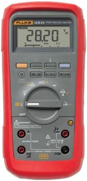
Figure 1: Front view of the Fluke 28IIEX/ETL Digital Multimeter. The image displays the device with its red protective holster, gray body, LCD screen showing '28.20 V AC', and the rotary dial for function selection. Below the dial are the input jacks for current, voltage, and common connections, along with safety warnings and certifications.
3.1 Key Features
- True-RMS measurements for accurate readings on linear and non-linear loads.
- Auto- and manual-ranging capabilities.
- Measures voltage, current, resistance, capacitance, frequency, temperature, conductance, and duty cycle.
- Performs continuity and diode tests.
- Low-pass filter for accurate voltage and frequency measurements on variable-speed motor drives.
- MIN/MAX/AVG and Peak Capture functions to record transients and measurement variations.
- Relative mode to remove test lead interference.
- Backlit keypad buttons and display for low-light conditions.
- Audible alarm for incorrect test lead connection.
4. Setup
4.1 Battery Installation
The Fluke 28IIEX/ETL requires four (4) AA alkaline batteries for operation. To install or replace batteries:
- Ensure the multimeter is turned OFF.
- Remove the protective rubber holster.
- Locate and open the battery compartment cover on the rear of the device.
- Insert four new AA alkaline batteries, observing the correct polarity markings.
- Securely close the battery compartment cover and reattach the holster.
4.2 Connecting Test Leads
Always connect test leads to the appropriate input jacks for the measurement being performed. The multimeter will sound an alarm if leads are connected incorrectly for the selected function.
- COM Jack: Connect the black test lead to the common (COM) jack for all measurements.
- VΩHz Jack: Connect the red test lead to this jack for voltage, resistance, frequency, capacitance, and diode tests.
- mAµA Jack: Connect the red test lead to this jack for current measurements up to 400mA. This input is fused.
- 10A Max Fused Jack: Connect the red test lead to this jack for current measurements up to 10A. This input is fused.
5. Operating Instructions
Turn the rotary switch to the desired function. The multimeter defaults to auto-ranging mode, automatically selecting the correct measurement range. Press the 'RANGE' button to switch to manual ranging.
5.1 Measuring Voltage (AC/DC)
- Connect the black lead to COM and the red lead to VΩHz.
- Turn the rotary switch to V~ (AC Voltage) or V- (DC Voltage).
- Connect the test leads across the circuit or component to be measured.
5.2 Measuring Current (mA/A/µA)
WARNING: Never attempt to measure current by connecting the multimeter in parallel with a voltage source. This can damage the meter and cause injury.
- Connect the black lead to COM. Connect the red lead to mAµA for small currents or 10A Max Fused for larger currents.
- Turn the rotary switch to mA/A~ (AC Current) or mA/A- (DC Current).
- Open the circuit and connect the multimeter in series with the load.
5.3 Measuring Resistance (Ω)
- Connect the black lead to COM and the red lead to VΩHz.
- Turn the rotary switch to Ω.
- Ensure the circuit is de-energized. Connect the test leads across the component.
5.4 Continuity Test
- Connect the black lead to COM and the red lead to VΩHz.
- Turn the rotary switch to the continuity symbol (speaker icon).
- Ensure the circuit is de-energized. Connect the test leads across the component. An audible tone indicates continuity.
5.5 Diode Test
- Connect the black lead to COM and the red lead to VΩHz.
- Turn the rotary switch to the diode symbol.
- Ensure the circuit is de-energized. Connect the test leads across the diode. The display shows the forward voltage drop.
5.6 Measuring Capacitance (F)
- Connect the black lead to COM and the red lead to VΩHz.
- Turn the rotary switch to the capacitance symbol.
- Ensure the capacitor is discharged before connecting the test leads.
5.7 Measuring Frequency (Hz) and Duty Cycle (%)
- Connect the black lead to COM and the red lead to VΩHz.
- Turn the rotary switch to Hz.
- Connect the test leads across the signal source. Press the '%' button to view duty cycle.
5.8 Measuring Temperature (°C/°F)
- Connect the K-type thermocouple (included) to the VΩHz and COM jacks, observing polarity.
- Turn the rotary switch to the temperature symbol.
- Place the thermocouple tip on the object to be measured.
5.9 Special Functions
- MIN MAX: Press to record minimum, maximum, and average readings over time.
- PEAK MIN MAX: Captures fast transients.
- REL Δ (Relative Mode): Subtracts the stored reading from subsequent readings, useful for nulling out test lead resistance.
- HOLD: Freezes the current display reading.
6. Maintenance
6.1 Cleaning
Wipe the case with a damp cloth and mild detergent. Do not use abrasives or solvents. Ensure the device is dry before use.
6.2 Battery Replacement
Refer to Section 4.1 for battery replacement instructions. Replace batteries when the low battery indicator appears on the display.
6.3 Fuse Replacement
WARNING: To prevent injury or damage to the multimeter, use only specified replacement fuses with the correct amperage, voltage, and interrupt ratings.
The Fluke 28IIEX/ETL has two internal fuses:
- 10A Max Fused: For the 10A current input.
- 400mA Fused: For the mA/µA current input.
Fuse replacement should only be performed by qualified personnel. Consult the full service manual or contact Fluke customer support for detailed instructions.
7. Troubleshooting
If the multimeter is not functioning as expected, review the following common issues:
- No display or faint display: Check batteries and replace if necessary.
- Incorrect readings: Ensure test leads are correctly connected, the function and range are appropriate for the measurement, and the circuit is de-energized for resistance/continuity/diode tests.
- Current measurement not working: Check the fuses for the respective current input (10A or 400mA). Replace if blown.
- Multimeter does not respond: Turn the unit off and then on again. If the issue persists, remove batteries for a few minutes and reinsert.
For persistent issues or complex problems, contact Fluke customer support.
8. Specifications
| Parameter | Specification |
|---|---|
| Maximum AC/DC Current Input | 10 A |
| Maximum AC/DC Voltage Input | 1000 V |
| Maximum Resistance Detected | 50 MΩ |
| Maximum Frequency | 199.99 kHz |
| Maximum Capacitance | 9999 µF |
| Temperature Range (excluding probe) | -200 to +1090 °C / -328 to +1994 °F |
| Duty Cycle Range | 0 to 99.9% |
| Display | LCD with 20,000-count resolution, two-level backlight |
| Power Supply | 4 AA batteries (Alkaline) |
| Safety Ratings | ATEX, NEC-500, IEXEx, IEC 61010, CAT III 1000V, CAT IV 600V, Pollution Degree 2 |
| Ingress Protection | IP67 (Waterproof, Dust-proof, Drop-proof) |
| Weight | 2.85 lbs (1.29 kg) |
| Dimensions (L x W x H) | 9.7 x 6.3 x 3.36 inches (24.6 x 16.0 x 8.5 cm) |
9. Warranty and Support
Fluke Corporation products are designed for reliability and performance. For warranty information, technical support, or service, please visit the official Fluke website or contact your local Fluke representative.
Official Fluke Website: www.fluke.com


