1. Introduction
This manual provides comprehensive instructions for the installation, operation, and maintenance of the KB Electronics KBIC-240D DC Motor Control. The KBIC-240D is an adjustable speed DC drive designed to control motors ranging from 1/50 HP to 1.0 HP (up to 2.0 HP with an auxiliary heat sink). It operates from either 115 VAC or 230 VAC and is suitable for 90 VDC and 180 VDC permanent magnet (PM) and shunt motors. It offers a 50:1 speed range with 1% load regulation.
For optimal performance and safety, please read this manual thoroughly before attempting installation or operation.
2. Safety Warnings
WARNING: Electrical shock hazard. Disconnect all power before servicing. Only qualified personnel should install or service this equipment.
- Always ensure the power supply is disconnected before making any electrical connections or adjustments to prevent electric shock.
- Improper installation or operation can result in serious injury or damage to the equipment.
- Shunt-wound motors may be damaged if the field remains energized with the motor stopped for an extended period of time, unless provided with external cooling. Refer to Table 1 for field connection details.
- Observe all local and national electrical codes during installation.
- Ensure proper grounding of the control and motor.

Figure 2.1: Manual cover indicating safety warnings and compatible models (KBIC-120, 125, 240, 225, 240D, 240DS).
3. Product Overview and Features
The KBIC-240D motor control offers robust performance and flexibility for various DC motor applications. Key features include:
- Adjustable speed control for 1/50 HP to 1.0 HP DC motors (up to 2.0 HP with auxiliary heat sink).
- Operates on 115 VAC or 230 VAC input.
- Compatible with 90 VDC and 180 VDC permanent magnet and shunt motors.
- 50:1 speed range with 1% load regulation.
- Auto Inhibit function.
- Voltage Following capability.
- MOV transient protection for enhanced durability.
- 5K speed potentiometer for primary speed adjustment.
- Trimpot adjustments for Minimum Speed (Min), Maximum Speed (Max), Acceleration (Accel), IR Compensation (IR), and Current Limit (CL).
- UL, CSA, CE, C-tick certified.

Figure 3.1: Angled view of the KBIC-240D control board, highlighting its compact design and electronic components.
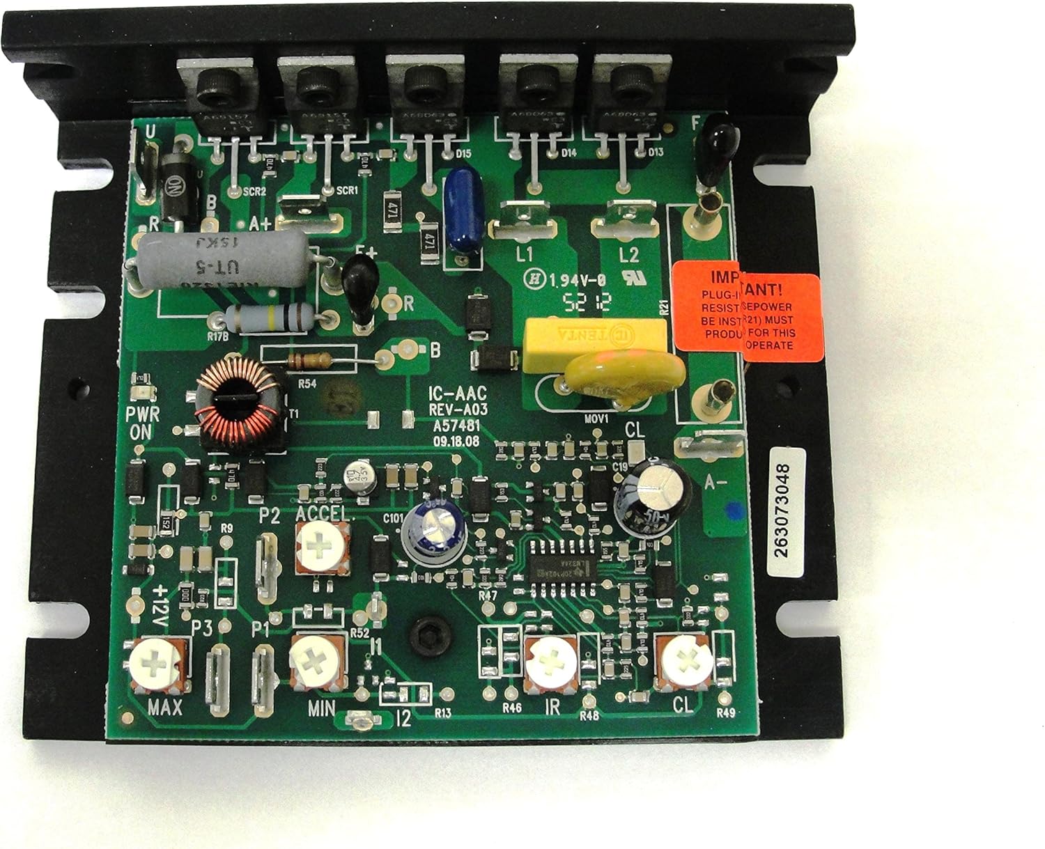
Figure 3.2: Top-down view of the KBIC-240D control board, illustrating the layout of trimpots and electrical connections.
4. Setup and Installation
Proper installation is crucial for the safe and effective operation of the KBIC-240D. Refer to the general connection diagram below for wiring details.

Figure 4.1: General Connection Diagram. This diagram illustrates the wiring for AC Line Input, Main Speed Potentiometer, Motor Armature, Motor Field (for Shunt Motors Only), and the location of trimpots (ACCEL, MAX, MIN, IR, CL).
4.1 Electrical Connections
- AC Line Input: Connect the appropriate AC line voltage (115 VAC or 230 VAC) to the designated terminals.
- Motor Armature: Connect the DC motor armature leads to the 'M' terminals.
- Motor Field (Shunt Motors Only): For shunt-wound motors, connect the motor field leads as indicated in the diagram. Refer to Table 1 for specific field connection details based on AC line voltage and desired field voltage.
- Main Speed Potentiometer: Connect the supplied 5K speed potentiometer to the P1, P2, P3 terminals for primary speed control.
- Inhibit Switch: An optional inhibit switch can be connected (open to run, close to stop) for external control.
4.2 Optional Components
- Plug-in Horsepower Resistor: Insert the correct Plug-in Horsepower Resistor to match the motor's HP rating. This resistor is supplied separately.
- Armature Fuse Holder Kit and Fuse: These are supplied separately and should be installed as shown in the diagram for circuit protection.
- AC Line Fuse Holder Kit and Fuse: These are supplied separately and should be installed for AC input protection.
- Auxiliary Heatsink: For motor applications requiring up to 2.0 HP, an auxiliary heatsink (e.g., KB Electronics 9861) is recommended and supplied separately. Refer to Figure 5.1 for mechanical specifications including heatsink dimensions.
4.3 Field Connections for Shunt-Wound Motors (Table 1)
The following table details the field connections for shunt-wound motors. Ensure correct connections to prevent motor damage.

Figure 4.2: Table 1 provides field connection details for shunt-wound motors based on AC line voltage and desired field voltage. Table 2 lists electrical ratings for various KBIC models, including the KBIC-240D, with and without an auxiliary heatsink.
| AC Line Voltage | Field Voltage (VDC) | Field Connection | Field Type |
|---|---|---|---|
| 115 | 100 | F+, F- | Full Voltage |
| 115 | 50 | F+, L1 | Half Voltage |
| 230 | 200 | F+, F- | Full Voltage |
| 230 | 100 | F+, L1 | Half Voltage |
CAUTION: Shunt-wound motors may be damaged if the field remains energized with the motor stopped for an extended period of time, unless provided with external cooling.
5. Operating Instructions
The KBIC-240D features several adjustments to fine-tune motor performance.
- Main Speed Potentiometer: This is the primary control for adjusting the motor speed. Rotate it to increase or decrease the motor's RPM.
- MIN Trimpot: Adjusts the minimum speed setting of the motor.
- MAX Trimpot: Adjusts the maximum speed setting of the motor.
- ACCEL Trimpot: Controls the acceleration rate of the motor.
- IR Trimpot (IR Compensation): Adjusts the IR compensation to maintain consistent motor speed under varying loads.
- CL Trimpot (Current Limit): Sets the maximum current the motor control will supply to the motor, protecting it from overload.
The CL LED will illuminate red when the motor is in an overload condition, indicating that the Current Limit setpoint has been reached.
6. Specifications
6.1 Mechanical Specifications

Figure 5.1: Mechanical Specifications. This diagram provides detailed dimensions for the KBIC-240D control unit, the main speed potentiometer, and the optional auxiliary heatsink. All dimensions are in inches.
- Control Dimensions: 4.30" x 3.60" x 1.30" (Length x Width x Height)
- Item Weight: Approximately 1 pound
- Material: Copper (for certain components)
- Mounting: Features 6 slots for mounting "A" and 3 tapped 6-32 holes for mounting "B". Fuse mounting has 2 tapped 6-32 holes.
6.2 Electrical Ratings (Table 2)
The following table provides the electrical ratings for the KBIC-240D, both with and without an auxiliary heatsink.
| Model No. | Part No. | AC Line Voltage (VAC) +/- 15% 50/60 Hz | Motor (VDC) | Rating Without Auxiliary Heat Sink | Rating With Auxiliary Heat Sink | Field Voltage (Shunt Wound Motor Only) (VDC) | ||||
|---|---|---|---|---|---|---|---|---|---|---|
| Max. AC Load Current (RMS Amps) | Max. DC Load Current (Avg. Amps) | Max. HP | Max. AC Load Current (RMS Amps) | Max. DC Load Current (Avg. Amps) | Max. HP | |||||
| KBIC-120 | 9429 | 115 | 0 - 90 | 9.0 | 6.0 | 0.5 | 18.0 | 12.0 | 1 | 50, 100 |
| KBIC-125 | 9433 | 115 | 0 - 90 | 12.0 | 8.0 | 0.75 | 24.0 | 16.0 | 1.5 | 50, 100 |
| KBIC-240 | 9428 | 208/230 | 0 - 180 | 9.0 | 6.0 | 1 | 18.0 | 12.0 | 2 | 100, 200 |
| KBIC-225 | 9432 | 208/230 | 0 - 180 | 12.0 | 8.0 | 1.5 | 24.0 | 16.0 | 3 | 100, 200 |
| KBIC-240D | 9464 | 115 | 0 - 90 | 9.0 | 6.0 | 0.5 | 18.0 | 12.0 | 1 | 50, 100 |
| KBIC-240D | 9464 | 208/230 | 0 - 180 | 9.0 | 6.0 | 1 | 18.0 | 12.0 | 2 | 100, 200 |
| KBIC-240DS | 9423 | 115, 208/230 | 0 - 90 | 9.0 | 6.0 | 0.5 | 18.0 | 12.0 | 1 | |
Note: The KBIC-240D (Part No. 9464) is highlighted in the table for easy reference. The maximum horsepower rating increases significantly with the use of an auxiliary heat sink.
7. Maintenance
The KBIC-240D DC Motor Control is designed for reliable operation with minimal maintenance. However, periodic checks can help ensure its longevity and performance.
- Cleaning: Keep the control unit free from dust and debris. Use a soft, dry brush or compressed air to clean the circuit board and heatsink fins. Ensure power is disconnected before cleaning.
- Connections: Periodically check all electrical connections for tightness. Loose connections can lead to intermittent operation or overheating.
- Environmental Conditions: Ensure the control is operating within its specified environmental conditions (temperature, humidity) to prevent premature failure.
- Inspection: Visually inspect the circuit board for any signs of damage, such as discolored components, bulging capacitors, or burnt traces. If any damage is observed, discontinue use and contact a qualified technician.
8. Troubleshooting
This section provides general troubleshooting tips for common issues. For complex problems, consult a qualified technician or contact KB Electronics support.
- Motor Not Running:
- Check if power is supplied to the control.
- Verify all wiring connections are correct and secure.
- Ensure the main speed potentiometer is not set to minimum.
- Check for blown fuses (AC line and armature fuses).
- If an inhibit switch is used, ensure it is in the "run" position.
- Motor Running Erratically or at Incorrect Speed:
- Check the speed potentiometer for proper function.
- Verify the MIN and MAX trimpot settings.
- Inspect motor brushes and commutator for wear (for brushed DC motors).
- Ensure the correct Plug-in Horsepower Resistor is installed.
- Motor Overheating or Tripping Current Limit (CL LED On):
- Check for excessive mechanical load on the motor.
- Verify the CL trimpot setting is appropriate for the motor and application.
- Ensure adequate ventilation for the motor and control.
- If operating at higher HP, confirm an auxiliary heatsink is installed.
- Check for short circuits in the motor or wiring.
9. Warranty and Support
Warranty information for the KBIC-240D DC Motor Control is typically provided with the product packaging or can be obtained directly from KB Electronics or your authorized distributor. Please retain your proof of purchase for warranty claims.
For technical support, service, or to inquire about replacement parts, please contact KB Electronics customer service or your product supplier. Refer to the official KB Electronics website for the most current contact information.