1. Introduction
This manual provides detailed instructions for the assembly, installation, operation, and maintenance of your Comet GP-9N Dual Band Base Antenna. Please read this manual thoroughly before proceeding with installation to ensure safe and correct usage.

Figure 1: Comet GP-9N Dual Band Base Antenna. This image shows the complete antenna assembly, highlighting its slender, multi-section design suitable for base station use.
The Comet GP-9N is a high-performance dual-band base/repeater antenna designed for 2-meter (144-148 MHz) and 70-centimeter (430-450 MHz) amateur radio bands. It features a heavy-duty fiberglass construction and an N-Type female connector for reliable performance.
2. Safety Information
Always observe the following safety precautions to prevent injury or damage to equipment:
- Power Lines: Never install the antenna near power lines. Contact with power lines can be fatal. Maintain a safe distance from all electrical wires.
- Weather Conditions: Avoid installation during lightning storms, high winds, or other severe weather conditions.
- Stable Mounting: Ensure the antenna is securely mounted to a sturdy mast or structure capable of withstanding wind loads.
- Grounding: Proper grounding of the antenna and mast is essential for lightning protection and safe operation. Consult local electrical codes.
- Tools: Use appropriate tools and safety gear, including gloves and eye protection, during assembly and installation.
- Assistance: Antenna installation, especially for tall antennas, often requires more than one person. Seek assistance to prevent accidents.
3. Package Contents
Verify that all components are present before beginning assembly:
- Antenna sections (typically 3 sections for the main fiberglass mast)
- Radial elements (ground plane elements)
- Mounting hardware (U-bolts, clamps, nuts, washers for mast attachment)
- Base connector assembly (with N-Type female connector)
- Instruction sheet (this manual)
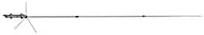
Figure 2: Detail of Comet GP-9N antenna component. This image shows a close-up of a section or connection point, illustrating the robust construction.
4. Setup
4.1. Assembly
- Carefully unpack all components and lay them out on a clean, flat surface.
- Identify the antenna sections. They are typically designed to fit together in a specific order (e.g., base, middle, top).
- Connect the antenna sections by aligning the internal and external sleeves. Secure them using the provided fasteners or by twisting until firmly seated, as per the design. Ensure all connections are tight to prevent moisture ingress and maintain structural integrity.
- Attach the radial elements to the base connector assembly. These typically screw into designated points around the base.
- Verify that the N-Type female connector at the base is clean and free of debris.
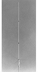
Figure 3: Comet GP-9N antenna sections before assembly. This image displays the individual fiberglass sections and radial elements, ready for connection.
4.2. Mounting
The GP-9N antenna is designed for mast mounting. The mast diameter should be between 1 1/2 and 2 1/4 inches.
- Select a suitable mounting location that is as high as possible, clear of obstructions, and away from power lines.
- Securely attach the antenna mounting bracket to your mast using the provided U-bolts and hardware. Ensure the mast is vertical and stable.
- Carefully raise the assembled antenna and attach it to the mounting bracket on the mast. Tighten all bolts firmly, but do not overtighten, to prevent damage to the fiberglass.
- Connect a high-quality 50-ohm coaxial cable with an N-Type male connector to the antenna's N-Type female connector. Use weather-sealing tape (e.g., self-amalgamating tape followed by UV-resistant electrical tape) to protect the connection from moisture.
- Route the coaxial cable away from the mast and secure it at regular intervals to prevent strain and movement.
- Ensure the mast and antenna system are properly grounded according to local electrical codes and best practices for lightning protection.

Figure 4: Comet GP-9N antenna installed on a mast. This image shows the antenna fully assembled and mounted, ready for operation.
5. Operating
Once the antenna is assembled, mounted, and connected to your radio equipment, it is ready for operation.
- Radio Connection: Connect the other end of your coaxial cable to the antenna port of your dual-band amateur radio transceiver.
- SWR Check: Before transmitting, always check the Standing Wave Ratio (SWR) using an SWR meter. The GP-9N is designed for an SWR of 1.5:1 or less across its operating bands (2M/70cm). High SWR can indicate an issue with the antenna, cable, or connection and can damage your radio.
- Frequency Bands: The antenna is optimized for 2-meter (144-148 MHz) and 70-centimeter (430-450 MHz) bands. Operate within these frequency ranges for optimal performance.
- Power Limit: Do not exceed the maximum power rating of 200 watts. Exceeding this limit can damage the antenna.
6. Maintenance
Regular maintenance will ensure the longevity and optimal performance of your antenna.
- Visual Inspection: Periodically inspect the antenna for any physical damage, cracks in the fiberglass, loose connections, or corrosion.
- Mounting Hardware: Check all mounting hardware (U-bolts, clamps) for tightness, especially after severe weather.
- Coaxial Connections: Inspect the coaxial cable and its connections for signs of wear, damage, or moisture ingress. Reapply weather-sealing tape if necessary.
- Cleaning: Clean the antenna with a mild soap and water solution if it becomes excessively dirty. Avoid abrasive cleaners.
7. Troubleshooting
Refer to the table below for common issues and their potential solutions:
| Problem | Possible Cause | Solution |
|---|---|---|
| High SWR (Standing Wave Ratio) |
|
|
| Poor signal reception/transmission |
|
|
| Antenna instability |
|
|
8. Technical Specifications
The following are the key technical specifications for the Comet GP-9N Dual Band Base Antenna:
- Coverage: 2M (144-148 MHz) / 70cm (430-450 MHz)
- Gain & Wave:
- 2M: 8.5dBi (5/8 wave x 3)
- 70cm: 11.9dBi (5/8 wave x 8)
- VSWR: 1.5:1 or less
- Max Power: 200 watts
- Length: 16 feet 9 inches (approximately 5.1 meters)
- Weight: 3 lbs. 8 oz. (approximately 1.59 kg)
- Mast Diameter: 1 1/2 - 2 1/4 inches (38 - 57 mm)
- Connector: Female N-Type
- Construction: Heavy-duty fiberglass, 3 sections
- Product Dimensions: 72 x 4 x 4 inches (packaged)
- Item Model Number: GP-9N
- UPC: 701630966055
9. Warranty and Customer Support
Information regarding the specific warranty period and customer support contact details for the Comet GP-9N antenna is not provided in the available product data. Please refer to the documentation included with your purchase or contact the retailer or manufacturer directly for warranty claims and technical assistance.


