Image: Dorman 'Control Arms' product line banner.
Introduction
This manual provides essential instructions for the proper installation, maintenance, and general information regarding the Dorman 521-794 Front Passenger Side Upper Suspension Control Arm and Ball Joint Assembly. This component is designed as a direct replacement for original equipment on specific vehicle applications, ensuring proper fit and function. Adherence to these instructions is crucial for safe and effective operation of your vehicle's suspension system.
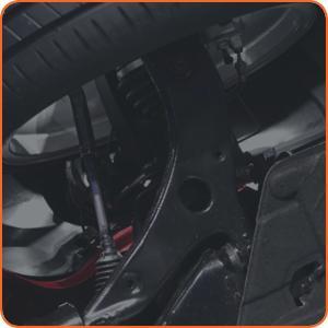
Image: A view of a vehicle's suspension, showing the location of a control arm.
Image: An illustrative diagram of a control arm's function in a vehicle's suspension.
Vehicle Compatibility
The Dorman 521-794 Control Arm and Ball Joint Assembly is compatible with the following vehicle models. Always verify fitment using your vehicle's make, model, and trim level before installation.
- Ford Fusion: 2007, 2008, 2009, 2010, 2011, 2012
- Mazda 6: 2006, 2007
- Mercury Milan: 2007, 2008, 2009, 2010, 2011
Safety Information
Automotive repair can be hazardous. Always follow proper safety procedures and use appropriate personal protective equipment (PPE) when working on your vehicle. If you are unsure about any step, consult a qualified mechanic.
- Wear safety glasses to protect your eyes from debris.
- Use jack stands to support the vehicle securely after lifting. Never rely solely on a jack.
- Ensure the vehicle is on a level surface and the parking brake is engaged.
- Disconnect the battery's negative terminal before working on electrical components.
- Refer to your vehicle's service manual for specific torque specifications and procedures.
- This product contains chemicals known to the State of California to cause cancer and birth defects or other reproductive harm (Proposition 65 warning). Wash hands after handling.
Package Contents
Verify that all components are present and undamaged before beginning installation.
- 1x Dorman 521-794 Front Passenger Side Upper Suspension Control Arm and Ball Joint Assembly

Image: The Dorman 521-794 Front Passenger Side Upper Suspension Control Arm and Ball Joint Assembly, showing the main component with pre-installed ball joint and bushings.

Image: A side view of the Dorman 521-794 Control Arm, highlighting its profile.
Installation Instructions
This section outlines the general procedure for replacing the front passenger side upper control arm. Specific steps may vary depending on your vehicle model. Always consult your vehicle's service manual for detailed instructions and torque specifications.
- Prepare the Vehicle:
- Park the vehicle on a level, firm surface.
- Engage the parking brake.
- Loosen the lug nuts on the front passenger side wheel.
- Raise the front of the vehicle using a floor jack and secure it with jack stands. Ensure the vehicle is stable.
- Remove the front passenger side wheel.
- Access the Control Arm:
- Locate the upper control arm. It connects the top of the steering knuckle to the vehicle frame.
- Support the lower control arm with a jack stand or floor jack to prevent the suspension from dropping excessively when components are disconnected.
- Disconnect the Ball Joint:
- Remove the cotter pin and castle nut from the upper ball joint stud where it connects to the steering knuckle.
- Use a ball joint separator tool or a pickle fork to separate the ball joint from the steering knuckle. Be careful not to damage the ball joint boot or other components if reusing.

Image: A hex nut, representative of the fasteners used to secure the ball joint.
- Remove the Control Arm Mounting Bolts:
- Locate the bolts securing the control arm to the vehicle frame or subframe. There are typically two bolts.
- Remove these bolts. Note their orientation for reinstallation.

Image: The Dorman 521-794 Control Arm, illustrating the bushing locations where it attaches to the vehicle frame.
- Remove the Old Control Arm:
- Carefully remove the old control arm from the vehicle.
- Compare the old control arm with the new Dorman 521-794 assembly to ensure they are identical.
- Install the New Control Arm:
- Position the new Dorman 521-794 control arm into place.
- Insert the mounting bolts through the bushings and into the frame. Hand-tighten them initially.
- Connect the new ball joint stud to the steering knuckle. Install the new castle nut and cotter pin. Torque the castle nut to the manufacturer's specification.
- Final Tightening:
- With the vehicle's weight on the suspension (or simulated by raising the lower control arm with a jack), torque the control arm mounting bolts to the vehicle manufacturer's specifications. This is crucial to prevent premature bushing wear.
- Reassembly:
- Reinstall the wheel and torque the lug nuts to specification.
- Lower the vehicle completely.
- Post-Installation:
- It is highly recommended to have a professional wheel alignment performed after replacing any suspension components to ensure proper vehicle handling and tire wear.
- Test drive the vehicle carefully to ensure proper function and no unusual noises.
Operation and Performance
Once correctly installed and aligned, the Dorman 521-794 Control Arm and Ball Joint Assembly will restore the intended geometry and function of your vehicle's front suspension. You should experience improved ride quality, directional stability, and predictable handling. Any unusual noises, vibrations, or steering issues after installation should be investigated immediately.
Maintenance
The Dorman 521-794 Control Arm and Ball Joint Assembly is designed for long-term durability. Regular inspection of suspension components is recommended as part of your vehicle's routine maintenance schedule.
- Visual Inspection: Periodically inspect the control arm, ball joint boot, and bushings for signs of wear, cracks, tears, or damage.
- Lubrication: The ball joint in this assembly is typically sealed and does not require periodic lubrication. If a grease fitting is present (not common on sealed units), apply appropriate grease as per vehicle manufacturer recommendations.
- Alignment: Ensure wheel alignment is checked and adjusted periodically, especially after hitting potholes or performing other suspension work.
Troubleshooting
| Symptom | Possible Cause | Solution |
|---|---|---|
| New noise (clunking, squeaking) after installation | Loose fasteners, improper torque, damaged component during installation, incorrect part. | Re-check all fasteners for proper torque. Inspect for any contact between components. Verify part compatibility. |
| Vehicle pulls to one side or uneven tire wear | Incorrect wheel alignment. | Perform a professional wheel alignment. |
| Difficulty installing ball joint into knuckle | Steering knuckle bore is corroded or damaged, incorrect angle. | Clean the knuckle bore. Ensure the ball joint stud is aligned correctly. Do not force. |
Specifications
| Feature | Detail |
|---|---|
| Brand | Dorman |
| Model Number | 521-794 |
| Part Position | Front Passenger Side Upper |
| Material | Alloy Steel |
| Fit Type | Vehicle Specific Fit |
| Item Weight | 4.2 pounds |
| Product Dimensions | 15.8 x 4.8 x 12.5 inches |
| UPC | 019495412434 |
| OEM Part Numbers | CA388B; CB76027; CMS76107; GS76107; RK620635; SK521794; 7E5Z3085L; GP9A34200A; GP9A34200B; GP9A34200C; GV2W34200 |
Warranty and Support
Dorman products are engineered for quality and reliability. For specific warranty information, please refer to the documentation included with your purchase or visit the official Dorman website. Dorman provides resources to support its products:
- Installation and Repair Training
- ASE Blue Seal Certified Technical Support
Image: Dorman's commitment to support, highlighting installation training and technical assistance.