1. Introduction and Overview
The Kyoritsu 4102A-H is a robust and reliable instrument designed for accurate measurement of earth resistance and earth voltage. This device performs three-pole earth resistance and two-pole voltage testing, essential for evaluating the grounding of electrical equipment and systems. Proper grounding helps mitigate power quality issues and enhances safety. Its compact, lightweight design features a shock-resistant casing and a taut-band movement for precise analog readings. This manual provides comprehensive instructions for the safe and effective use of your Kyoritsu 4102A-H.
2. Safety Information
Always read and understand all safety warnings and operating instructions before using this instrument.
- This instrument is designed for use by qualified personnel only.
- Do not use the tester if it appears damaged or if the test leads are compromised.
- Ensure all connections are secure before performing any tests.
- Avoid contact with live circuits. Always assume circuits are live until proven otherwise.
- The Kyoritsu 4102A-H has an IP 54 rating, indicating limited protection against dust ingress and protection against water splashes. Do not immerse the device in water.
- This device is CE compliant, designed to safety standard IEC 61557, and rated as CAT III 300V. Adhere to these safety standards during operation.
- Replace batteries promptly when the battery check indicates low power.
3. Package Contents
Verify that all items listed below are present in your package:
- Kyoritsu 4102A-H Earth Ground Test Meter
- (3) 7095A Earth Resistance Test Leads (Red 20m, Yellow 10m, Green 5m)
- 7127A Simplified Measurement Probe Set
- (2) 8032 Auxiliary Earth Spikes
- 9164 Hard Carrying Case
- Neck Strap
- (6) AA Dry Cell Batteries
- Instruction Manual (this document)
4. Product Features
- Three-Pole Earth Resistance Testing: Measures earth resistance using the standard three-pole method.
- Two-Pole Earth Voltage Testing: Capable of measuring earth voltage.
- Low Measuring Current: Utilizes a 2mA measuring current, which prevents tripping of ground fault circuit interrupters (GFCIs) during testing.
- Auxiliary Earth Spike Warning: Provides an automatic warning if the resistance of the auxiliary earth spikes exceeds acceptable tolerance levels, ensuring measurement accuracy.
- OK Light Indicator: Verifies proper connection between auxiliary earth resistance and lead wires to the terminals.
- Rugged Design: Small, lightweight, and housed in a shock-resistant case for durability.
- Environmental Protection: IP 54 rated for protection against dust and water splashes.
- Safety Compliance: CE compliant, designed to IEC 61557, and rated CAT III 300V.
5. Setup
5.1 Battery Installation
- Ensure the tester is switched OFF.
- Locate the battery compartment cover on the back of the unit.
- Open the cover and insert six (6) AA 1.5V batteries, observing correct polarity (+/-).
- Securely close the battery compartment cover.
5.2 Connecting Test Leads and Auxiliary Earth Spikes
For three-pole earth resistance measurement:
- Connect the green test lead (5m) to the 'E' (Earth) terminal on the tester and to the earth electrode under test.
- Connect the yellow test lead (10m) to the 'P' (Potential) terminal on the tester and to the auxiliary earth spike P.
- Connect the red test lead (20m) to the 'C' (Current) terminal on the tester and to the auxiliary earth spike C.
- Ensure auxiliary earth spikes P and C are driven into the ground at appropriate distances from the earth electrode under test, typically in a straight line. Refer to standard earth resistance testing practices for optimal spacing.
For two-pole earth voltage measurement:
- Connect the green test lead to the 'E' terminal.
- Connect the yellow test lead to the 'P' terminal.
- Connect the other ends of the leads to the points where voltage is to be measured.
6. Operating Instructions
6.1 Powering On and Battery Check
- Turn the rotary switch to the 'BATT. CHECK' position.
- Observe the analog meter. The needle should point to the 'BATT GOOD' section. If it falls below this, replace the batteries.
6.2 Movement Zero Adjustment
Before performing resistance measurements, ensure the meter needle is at the zero position. If not, use the 'MOVEMENT ZERO' adjustment screw to align it.
6.3 Earth Voltage Measurement
- Connect the test leads as described in Section 5.2 for two-pole measurement.
- Turn the rotary switch to the 'EARTH VOLTAGE' position.
- Read the voltage value directly from the 'O.V' scale on the analog meter. The range is 0-30V AC (50, 60Hz).
6.4 Earth Resistance Measurement
- Connect the test leads and auxiliary earth spikes as described in Section 5.2 for three-pole measurement.
- Select an appropriate measurement range using the rotary switch: '×1Ω', '×10Ω', '×100Ω', or '×1000Ω'. Start with the highest range if the resistance value is unknown.
- Press and hold the 'PRESS TO TEST' button. The 'OK' light should illuminate, indicating proper connections. If the 'OK' light does not illuminate or the auxiliary earth spike warning activates, check your connections and spike placement.
- While holding the 'PRESS TO TEST' button, read the value from the analog meter's resistance scale and multiply it by the selected range multiplier (e.g., if the meter reads '5' on the '×10Ω' range, the resistance is 50Ω).
- For continuous measurement, press the 'PRESS TO TEST' button and then slide the 'LOCK' switch to the locked position. Release the 'PRESS TO TEST' button. The measurement will continue until the 'LOCK' switch is disengaged.
- After measurement, release the 'PRESS TO TEST' button or unlock the switch.
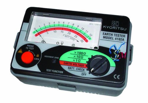
Figure 1: Front view of the Kyoritsu 4102A-H Ground Resistance Tester. The image displays the analog meter with scales for Earth Voltage (O.V) and resistance (0-12, 0-120, 0-1200 Ohm), the 'PRESS TO TEST' button with 'LOCK' switch, the 'MOVEMENT ZERO' adjustment, and the rotary selector for 'TEST FUNCTION' including '×1Ω', '×10Ω', '×100Ω', '×1000Ω' ranges, 'EARTH VOLTAGE', 'BATT. CHECK', and 'OFF'. The Kyoritsu logo and model number 4102A are visible.
7. Measurement Principles
Earth resistance testing is crucial for ensuring the safety and proper functioning of electrical systems. The Kyoritsu 4102A-H primarily uses the three-pole (fall-of-potential) method. This method involves injecting a current into the earth via a current spike (C) and measuring the voltage drop between the earth electrode under test (E) and a potential spike (P). By applying Ohm's Law (R = V/I), the instrument calculates the earth resistance. This method helps to accurately determine the resistance of the earth electrode to the general mass of the earth, which is vital for dissipating fault currents, lightning strikes, and static discharges.
8. Maintenance
8.1 Cleaning
Wipe the instrument with a soft, dry cloth. For stubborn dirt, use a cloth lightly dampened with water and a mild detergent. Do not use abrasive cleaners or solvents.
8.2 Battery Replacement
Replace batteries as soon as the 'BATT. CHECK' indicates low power to ensure accurate measurements and prevent leakage. Refer to Section 5.1 for battery installation instructions.
8.3 Storage
When not in use for extended periods, remove the batteries to prevent leakage. Store the instrument in its hard carrying case in a cool, dry place, away from direct sunlight and extreme temperatures.
8.4 Calibration
For continued accuracy, periodic calibration by a qualified service center is recommended. Refer to Kyoritsu's official support channels for calibration services.
9. Troubleshooting
- No Display/Power: Check battery installation and ensure batteries are fresh. Verify the rotary switch is not in the 'OFF' position.
- 'OK' Light Not Illuminating: This indicates an issue with the test lead connections or auxiliary earth spike placement. Ensure all leads are securely connected to the correct terminals and the spikes are properly driven into the ground.
- Auxiliary Earth Spike Warning: If this warning activates, the resistance of the auxiliary earth spikes is too high. Try relocating the spikes to an area with better conductivity or moisten the ground around them.
- Inaccurate Readings: Ensure the correct range is selected. Check for proper lead connections and spike placement. Verify battery strength. Ensure the 'MOVEMENT ZERO' is adjusted correctly.
- Meter Needle Does Not Move: Check battery status. Ensure the 'PRESS TO TEST' button is fully depressed or the 'LOCK' switch is engaged.
10. Specifications
| Parameter | Value |
|---|---|
| Earth Resistance Range | 0-12Ω / 0-120Ω / 0-1200Ω |
| Earth Voltage Range | 0-30V AC (50, 60Hz) |
| Accuracy | ± 3% full scale |
| Withstand Voltage | 3700V AC for 1 minute |
| Measuring Current | 2mA (does not trip GFCIs) |
| Power Source | (6) R6P (AA) 1.5V batteries |
| Weight | 600g (approx. 0.7 lbs) |
| Dimensions (H x W x D) | 105 x 158 x 70mm |
| IP Rating | IP 54 |
| Safety Rating | CE compliant, IEC 61557, CAT III 300V |
| Manufacturer | Kyoritsu (Founded 1940, Tokyo, Japan) |
11. Warranty and Support
For warranty information, technical support, or service inquiries, please contact your authorized Kyoritsu dealer or the manufacturer directly. Retain your proof of purchase for warranty claims. Kyoritsu is a reputable manufacturer of electrical testing and measurement instruments, headquartered in Tokyo, Japan.