1. Introduction
The Clear-Com MS-702 is a compact, feature-laden, single rack-space intercom main station designed for professional communication environments. This 2-channel headset/speaker main station includes a built-in 2-amp power supply and is UL Listed. It is capable of supporting various Clear-Com components, including up to 40 RS-701 beltpacks, 10 speaker stations, or 12 headset stations across its two independent channels.
This manual provides essential information for the proper setup, operation, and maintenance of your MS-702 intercom main station.
2. Product Overview
2.1 Front Panel Controls and Connectors
The front panel of the MS-702 provides access to essential controls for operation and connections for local users.
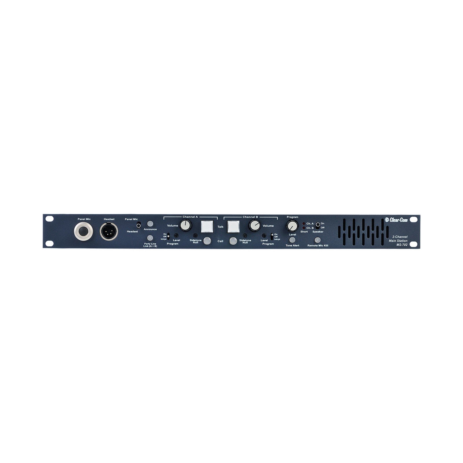
Figure 1: Front view of the Clear-Com MS-702 main station, showing headset connectors, volume controls, talk buttons, and channel indicators.
- Panel Mic (XLR): Input for a gooseneck microphone.
- Headset (4-pin XLR): Connector for a headset.
- Volume (Channel A & B): Adjusts the listening level for each channel.
- Talk (Channel A & B): Activates the microphone for communication on the respective channel.
- Call (Channel A & B): Sends a call signal to all stations on the respective channel.
- Sidetone Null (Channel A & B): Adjusts the sidetone level to prevent feedback in the headset.
- Program (Level & On/Off): Controls the level and activation of external program audio input.
- Announce: Activates the announce output.
- Tone Alert: Activates an audible tone alert.
- Remote Mic Kill: Disables all remote microphones.
- Party Line Link (A+B): Links Channel A and Channel B.
- Speaker (On/Off): Toggles the internal speaker.
- Ch. A / Ch. B (On/Off): Activates or deactivates the respective intercom channel for the internal speaker.
2.2 Rear Panel Connectors
The rear panel houses all primary connections for power, intercom lines, and auxiliary audio inputs/outputs.

Figure 2: Rear view of the Clear-Com MS-702 main station, showing power input, intercom channel connections, program input, and auxiliary outputs.
- Power Input (IEC): Standard AC power connector with integrated fuse holder and power switch.
- Intercom Channel A & B (XLR 3-pin): Connectors for linking to other intercom stations, beltpacks, or speaker stations. Each channel typically uses XLR-3 connectors for audio and power.
- Term A / Term B (On/Off): Termination switches for each intercom channel. Set to 'On' if this is the last station on the line.
- Program Input (XLR 3-pin): Input for external audio sources to be mixed into the intercom channels.
- Announce Out (XLR 3-pin): Output for the announce function.
- Relay Out (RCA): Relay output for external control.
- Hot Mic / C-C IFB System (RCA): Connectors for specific Clear-Com IFB (Interruptible Foldback) systems or hot mic applications.
- Intercom Wiring (DIP Switches): Configuration switches for intercom line wiring (e.g., 1=Gnd, 2=Pwr, 3=Audio). Refer to specific wiring diagrams for your system.
- Alert Volume: Adjusts the volume of the alert tone.
3. Setup and Installation
3.1 Rack Mounting
The MS-702 is designed for standard 1RU (1 Rack Unit) rack mounting. Secure the unit into a standard 19-inch equipment rack using appropriate rack screws. Ensure adequate ventilation around the unit.
3.2 Power Connection
- Ensure the power switch on the rear panel is in the 'Off' position.
- Connect the supplied IEC power cable to the power input on the rear panel.
- Plug the other end of the power cable into a suitable AC power outlet. The MS-702 operates on standard AC voltage.
3.3 Intercom System Wiring
The MS-702 supports two independent intercom channels. Connect your beltpacks, speaker stations, or other intercom devices to the 'Intercom Channel A' and 'Intercom Channel B' XLR 3-pin connectors on the rear panel.
- Use high-quality, shielded XLR cables for all intercom connections.
- For optimal performance, ensure proper termination. If the MS-702 is the last station on an intercom line, set the corresponding 'Term A' or 'Term B' switch to 'On'. Otherwise, set it to 'Off'.
- Consult the DIP switch settings for 'Intercom Wiring' on the rear panel to match your system's pin configuration (typically 1=Ground, 2=Power, 3=Audio).
3.4 Headset and Panel Microphone Connection
- Connect a compatible 4-pin XLR headset to the 'Headset' connector on the front panel.
- If using a gooseneck microphone, connect it to the 'Panel Mic' XLR connector on the front panel.
3.5 Program Audio Input
To feed external audio (e.g., music, broadcast feed) into the intercom system, connect your audio source to the 'Program Input' XLR 3-pin connector on the rear panel. Use the 'Program Level' control on the front panel to adjust the input volume and the 'Program On/Off' switch to enable or disable the feed.
4. Operation
4.1 Powering On/Off
To power on the unit, flip the power switch on the rear panel to the 'On' position. To power off, flip the switch to 'Off'.
4.2 Basic Communication
- Connect your headset or use the panel microphone.
- Adjust the 'Volume' control for Channel A and/or Channel B to a comfortable listening level.
- Press and hold the 'Talk' button for the desired channel (A or B) to speak to other stations on that channel. Release to listen.
- If using the internal speaker, ensure the 'Speaker' switch is 'On' and select 'Ch. A' or 'Ch. B' as desired.
4.3 Sidetone Adjustment
The 'Sidetone Null' control allows you to adjust the level of your own voice heard in your headset. Adjust this control to a comfortable level to prevent feedback or an overly loud self-monitor.
4.4 Using the Call Function
Press the 'Call' button for Channel A or B to send an audible and/or visual alert to all connected stations on that channel. This is useful for attracting attention without speaking.
4.5 Program Audio Integration
If program audio is connected to the rear panel, activate it using the 'Program On/Off' switch on the front panel. Adjust the 'Program Level' knob to mix the external audio into the intercom channels at the desired volume.
4.6 Announce Function
Press the 'Announce' button to activate the announce output. This can be used to send audio to an external public address system or other designated output.
4.7 Remote Mic Kill
The 'Remote Mic Kill' button allows the operator to remotely disable all microphones on connected beltpacks or other remote stations. This is useful for managing open microphones in a live production environment.
5. Maintenance
The Clear-Com MS-702 is designed for reliable operation with minimal maintenance. Follow these guidelines to ensure longevity:
- Cleaning: Disconnect power before cleaning. Use a soft, dry cloth to wipe the exterior. Avoid abrasive cleaners, solvents, or excessive moisture.
- Ventilation: Ensure that the ventilation openings are not obstructed. Proper airflow prevents overheating.
- Storage: Store the unit in a cool, dry environment away from direct sunlight and extreme temperatures when not in use for extended periods.
- Fuse Replacement: If the unit does not power on, check the fuse located within the IEC power input module on the rear panel. Replace with a fuse of the same type and rating only.
6. Troubleshooting
If you encounter issues with your MS-702, refer to the following common troubleshooting steps:
| Problem | Possible Cause | Solution |
|---|---|---|
| Unit does not power on. | No AC power; Blown fuse. | Check power cable connection and outlet. Inspect and replace fuse if necessary. |
| No audio from headset/speaker. | Volume too low; Headset/mic not connected; Channel not selected; Faulty cable. | Increase volume. Ensure headset/mic is properly connected. Select the correct channel (A or B). Test with a different cable or headset. |
| Cannot talk on a channel. | 'Talk' button not pressed; Microphone issue. | Ensure 'Talk' button is pressed. Check headset microphone connection and functionality. |
| Hum or noise on intercom line. | Improper grounding; Cable issues; Incorrect termination. | Check all cable connections for proper shielding and grounding. Ensure termination switches are set correctly. |
| Sidetone feedback. | Sidetone level too high. | Adjust the 'Sidetone Null' control to reduce feedback. |
If the problem persists after attempting these solutions, contact Clear-Com technical support or your authorized dealer for further assistance.
7. Specifications
| Feature | Detail |
|---|---|
| Model Number | MS-702 |
| Channels | 2 |
| Power Supply | Built-in 2-amp |
| Rack Mount | 1RU (1 Rack Unit) |
| Compatible Devices | Beltpack, Headset, Microphone, Speaker |
| Connectivity Technology | XLR, RCA, AUX |
| Audio Input | XLR, RCA |
| Manufacturer | Clear-Com |
| UPC | 642892781263 |
| GTIN | 642892781263 |
8. Warranty and Support
For detailed warranty information, please refer to the warranty card included with your product or visit the official Clear-Com website. Warranty terms and conditions may vary by region and retailer.
If you require technical assistance, have questions about your MS-702, or need to arrange for service, please contact Clear-Com customer support or your authorized Clear-Com dealer. Contact information can typically be found on the Clear-Com website.