1. Introduction
This manual provides detailed instructions for the installation, operation, and maintenance of your Proselect Non-Programmable 1 Stage Heating 1 Stage Cooling Thermostat. Please read this manual thoroughly before installation and operation to ensure proper function and safety.
This thermostat is designed for use with 1-stage heating and 1-stage cooling systems, including gas, electric, or heat pump systems.
2. Safety Information
- Always turn off power to the heating/cooling system at the main fuse or circuit breaker panel before installing or servicing the thermostat.
- Installation should be performed by a qualified technician if you are unsure about the wiring procedures.
- Do not short (jumper) the electrical terminals on the control board. This can damage the thermostat and the system.
- Ensure all wiring connections are secure and properly insulated to prevent electrical shorts.
- This thermostat operates on 24 Volts. Do not connect to line voltage (120V/240V).
3. Package Contents
Verify that all items are present in the package:
- Proselect Non-Programmable Thermostat Unit
- Mounting Hardware (screws and wall anchors)
- User Manual (this document)
4. Installation
4.1 Location Selection
Choose a location for the thermostat that is:
- On an inside wall, approximately 5 feet (1.5 meters) above the floor.
- Away from direct sunlight, drafts, or heat sources (e.g., lamps, appliances, fireplaces).
- Away from areas with poor air circulation.
4.2 Mounting the Thermostat
- Turn off power to the heating/cooling system at the main fuse or circuit breaker.
- Remove the old thermostat (if applicable) and disconnect its wiring, noting the terminal connections.
- Separate the front cover of the new Proselect thermostat from its base.
- Position the thermostat base on the wall, using the old mounting holes if possible, or mark new ones.
- Drill holes (if necessary) and insert wall anchors. Secure the thermostat base to the wall using the provided screws.
4.3 Wiring
This thermostat supports dual-power options: hardwired (24V AC) or battery powered (2 AA batteries, not included). It features separate O and B terminals for heat pump applications.
| Terminal | Description |
|---|---|
| R | 24V AC (Heating/Cooling Power) |
| C | Common (for continuous 24V power, optional if using batteries) |
| W | Heat Relay |
| Y | Cool Relay |
| G | Fan Relay |
| O | Reversing Valve (Cooling Changeover - Heat Pumps) |
| B | Reversing Valve (Heating Changeover - Heat Pumps) |
Connect the wires from your system to the corresponding terminals on the thermostat base. Ensure wires are securely fastened.
After wiring, snap the front cover back onto the base. Restore power to the system.
5. Setup and Initial Operation
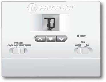
Figure 1: Proselect Non-Programmable Thermostat Front Panel. This image displays the thermostat's large digital display, which shows the current temperature and mode (e.g., "70 HEAT"). Below the display are three buttons: an up arrow, a down arrow, and a central button (likely for menu or confirmation). To the left, a horizontal slide switch controls the system mode with options for "COOL", "OFF", and "HEAT". To the right, another horizontal slide switch controls the fan mode with options for "AUTO" and "ON". A small "RESET" button is also visible near the top right.
5.1 Powering the Thermostat
The thermostat can be powered by 24V AC (hardwired) or by two AA batteries (not included). If using batteries, open the easy access front battery door and insert two fresh AA alkaline batteries, observing polarity. The large display will illuminate upon successful power-up.
5.2 Setting the Temperature
- Use the Up Arrow (▲) button to increase the desired temperature set point.
- Use the Down Arrow (▼) button to decrease the desired temperature set point.
- The large display will show the set temperature briefly, then revert to displaying the current room temperature.
5.3 System Mode Selection
Use the SYSTEM switch located on the left side of the thermostat to select the desired operating mode:
- COOL: The system will operate in cooling mode.
- OFF: The heating and cooling system is turned off.
- HEAT: The system will operate in heating mode.
5.4 Fan Mode Selection
Use the FAN switch located on the right side of the thermostat to select the desired fan operation:
- AUTO: The fan runs only when the heating or cooling system is actively operating. This is the most common setting.
- ON: The fan runs continuously, regardless of whether the heating or cooling system is active.
6. Operating Features
- Large Display with Bright Blue Backlight: The thermostat features a large, easy-to-read LCD display with a bright blue backlight for visibility in various lighting conditions. The backlight activates when buttons are pressed.
- Adjustable Temperature Set Point Limits: This feature allows you to set minimum and maximum temperature limits to prevent the set point from being adjusted outside a desired range. Consult the advanced settings section (if applicable, or refer to manufacturer's website for detailed instructions on setting limits).
- Non-Volatile Memory: User settings are retained even during power outages or battery changes, thanks to non-volatile memory.
- Compressor Short Cycle Protection: This built-in feature prevents damage to your compressor by delaying its restart for a few minutes after it has been turned off. This is a normal operation and ensures the longevity of your HVAC system.
- Separate Heating and Cooling Set Points: The thermostat maintains distinct set points for heating and cooling modes.
7. Maintenance
- Battery Replacement: If using battery power, replace the two AA batteries annually or when the low battery indicator appears on the display. Use the easy access front battery door for convenience.
- Cleaning: Clean the thermostat's exterior with a soft, damp cloth. Do not use abrasive cleaners or solvents.
- Air Vents: Ensure the small vents on the thermostat casing are not obstructed, as these allow the thermostat to sense room temperature accurately.
8. Troubleshooting
| Problem | Possible Cause | Solution |
|---|---|---|
| Display is blank or dim. | Low or dead batteries; no 24V AC power. | Replace batteries. Check circuit breaker for HVAC system. Ensure 24V AC wiring is correct. |
| System (heating/cooling) does not turn on. | System switch in OFF position; set temperature not met; circuit breaker tripped; wiring issue. | Set system switch to HEAT or COOL. Adjust set point. Check circuit breaker. Verify wiring connections. Allow for compressor short cycle delay. |
| Fan does not turn on in AUTO mode. | System not actively heating/cooling. | This is normal. Fan will only run when heating/cooling is active. Switch to ON for continuous fan. |
| Inaccurate temperature reading. | Thermostat exposed to direct sunlight, drafts, or heat sources. | Relocate thermostat if possible. Ensure vents are clear. |
| Thermostat resets unexpectedly. | Power fluctuation; internal error. | Press the RESET button (small hole, may require a paperclip). If issue persists, contact support. |
9. Specifications
- Model: PSTS11NP
- Power Source: 24V AC (Hardwired) or 2 AA Alkaline Batteries (not included)
- Compatibility: 1 Stage Heating, 1 Stage Cooling Systems (Gas, Electric, Heat Pump)
- Temperature Control Range: Typically 45°F to 90°F (7°C to 32°C) - Exact range may vary slightly, refer to product packaging.
- Dimensions: Approximately 12.7 x 3.18 x 9.53 cm (5 x 1.25 x 3.75 inches)
- Weight: Approximately 454 g (1 lb)
- Display: Large LCD with Bright Blue Backlight
- Special Features: Non-Volatile Memory, Compressor Short Cycle Protection, Easy Access Front Battery Door, Separate O and B terminals.
10. Warranty and Support
For warranty information and technical support, please refer to the contact details provided on the product packaging or visit the official Proselect website. Keep your purchase receipt as proof of purchase for warranty claims.
Manufacturer: Pro Select
Part Number: PSTS11NP


