1. Introduction
This manual provides instructions for the installation, operation, and maintenance of the Functional Devices (RIB) PSH100A Enclosed Single 100VA 120 to 24Vac UL Class 2 Power Supply. The PSH100A is designed to convert 120 Vac input power to a stable 24 Vac output, suitable for various low-voltage applications requiring a UL Class 2 power source.
Please read this manual thoroughly before installation and operation to ensure safe and efficient use of the product.
2. Safety Information
WARNING: Risk of Electric Shock. Disconnect power before installation or servicing.
- Installation and servicing must be performed by qualified personnel only.
- Adhere to all national and local electrical codes.
- Do not exceed the specified voltage and current ratings of the device.
- Ensure proper grounding where required.
- Do not operate the device if it appears damaged.
3. Setup and Installation
The PSH100A power supply is housed in a metal enclosure for protection and ease of mounting.
3.1. Mounting
The enclosure is designed for surface mounting. Select a suitable location that is dry, well-ventilated, and accessible for wiring and inspection. Use appropriate fasteners (not included) to secure the enclosure to a wall or panel through the pre-drilled mounting holes.
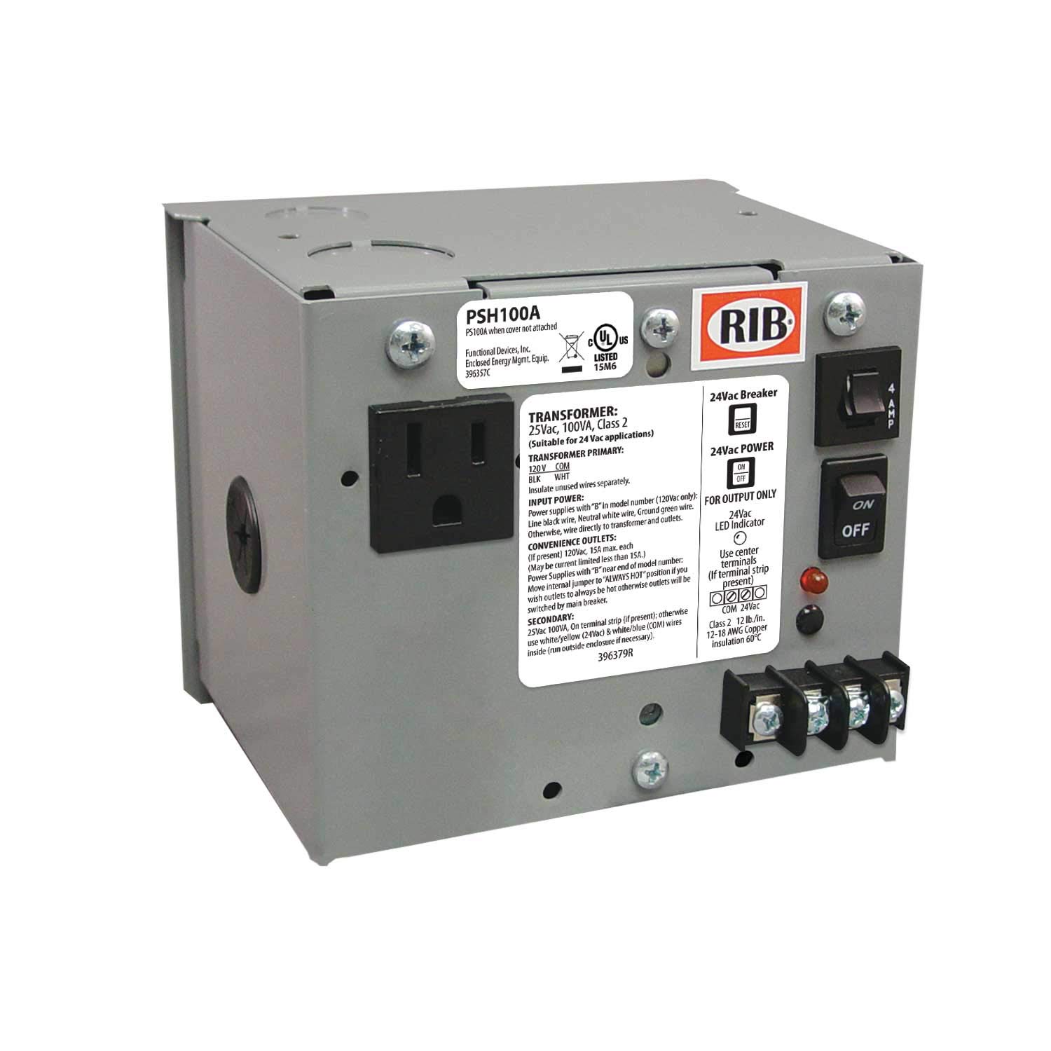
Figure 1: Functional Devices PSH100A Enclosed Power Supply. This image shows the metal enclosure of the power supply, typically with conduit knockouts and terminal block access for wiring.
3.2. Wiring
Ensure all power is disconnected at the circuit breaker before proceeding with wiring.
- Open the enclosure cover to access the terminal block.
- Input Wiring (120 Vac): Connect the 120 Vac line voltage to the designated input terminals. Typically, these are marked "L" (Line) and "N" (Neutral) or similar. Ensure proper polarity.
- Output Wiring (24 Vac): Connect the load requiring 24 Vac to the designated output terminals. These are usually marked "24VAC" or similar.
- Grounding: Connect the system ground to the grounding terminal within the enclosure, if provided and required by local codes.
- Verify all connections are secure and correct.
- Close the enclosure cover.
4. Operating Instructions
Once the PSH100A power supply is correctly installed and wired, restore power to the circuit. The unit will immediately begin providing 24 Vac power at its output terminals. The PSH100A is designed for continuous operation and does not require any user interaction during normal use.
- The power supply is a Class 2 device, meaning its output is inherently limited to prevent electric shock and fire hazards.
- Ensure the connected load does not exceed the 100 VA (Volt-Ampere) rating of the power supply.
5. Maintenance
The PSH100A power supply is generally maintenance-free. However, periodic inspection is recommended to ensure optimal performance and safety.
- Annual Inspection: Visually inspect the enclosure for any signs of physical damage, corrosion, or overheating.
- Wiring Check: With power disconnected, verify that all wiring connections remain tight and secure.
- Cleaning: If necessary, gently clean the exterior of the enclosure with a dry, soft cloth. Do not use liquid cleaners or solvents.
WARNING: Do not attempt to open or repair the internal components of the power supply. Refer all servicing to qualified personnel.
6. Troubleshooting
If the PSH100A power supply is not functioning as expected, refer to the following troubleshooting steps:
- No Output Voltage:
- Verify that the 120 Vac input power is present at the input terminals using a multimeter.
- Check the circuit breaker supplying power to the unit.
- Inspect all wiring connections for looseness or damage.
- Ensure the load connected to the output is not short-circuited or drawing excessive current, which could trigger internal protection.
- Overheating:
- Ensure the power supply is installed in a location with adequate ventilation.
- Verify that the connected load does not exceed the 100 VA rating of the power supply. Excessive load can cause overheating.
If the issue persists after performing these steps, contact Functional Devices, Inc. technical support.
7. Specifications
| Model Number | PSH100A |
| Input Voltage | 120 Vac (Minimum: 120 Vac, Maximum: 120 Vac) |
| Output Voltage | 24 Vac |
| Output Power | 100 VA (Volt-Ampere) / 100 Watts |
| UL Rating | UL Class 2 |
| Dimensions (L x W x H) | 5 x 5 x 5 inches |
| Item Weight | 5 pounds |
| Enclosure | Metal Enclosed |
| Manufacturer | Functional Devices, Inc. |
| Brand | RIB |
| Compatible Devices | Computer Systems, Components, or Devices requiring 24VAC power |
8. Warranty Information
Specific warranty details for the PSH100A power supply are provided by the manufacturer, Functional Devices, Inc. Please refer to the documentation included with your purchase or visit the official Functional Devices, Inc. website for the most current warranty policy and registration information.
9. Technical Support
For technical assistance, troubleshooting beyond the scope of this manual, or inquiries regarding your Functional Devices (RIB) PSH100A power supply, please contact Functional Devices, Inc. directly.
Contact information can typically be found on the manufacturer's website or on the product packaging.


