1. Introduction
This manual provides essential instructions for the safe and effective operation of the Amprobe AM-570 Industrial Digital Multimeter. The AM-570 is designed for professionals requiring accurate and reliable measurements in various electrical, HVAC/R, and industrial maintenance applications. Please read this manual thoroughly before using the device to ensure proper function and safety.
2. Safety Information
To prevent electric shock or personal injury, and to avoid damage to the meter or the equipment under test, observe the following safety guidelines:
- Always adhere to local and national safety codes.
- The Amprobe AM-570 is rated for CAT IV 600 V and CAT III 1000 V. Do not exceed these ratings.
- Inspect test leads for damaged insulation or exposed metal before use. Replace damaged leads immediately.
- Ensure the function switch is in the correct position for the measurement being performed.
- Do not apply more than the rated voltage between terminals or between any terminal and ground.
- Use caution when working with voltages above 30 V AC RMS, 42 V peak, or 60 V DC. These voltages pose a shock hazard.
- Disconnect power to the circuit and discharge all high-voltage capacitors before performing resistance, continuity, diode, or capacitance tests.
- Do not operate the meter if it appears damaged or if it is not operating properly.
- Replace the battery as soon as the low battery indicator appears to ensure accurate readings.
- When servicing the meter, use only specified replacement parts.
3. Package Contents
Verify that all items listed below are present and undamaged:
- Amprobe AM-570 Industrial Digital Multimeter
- Test Leads (one pair, red and black)
- K-Type Thermocouple Probes (two)
- Carrying Case
- 9V Battery (pre-installed or included separately)
- User Manual (this document)

Image 3.1: The Amprobe AM-570 Digital Multimeter shown with its standard accessories, including test leads, two K-type thermocouple probes, and a soft carrying case.
4. Product Features
The Amprobe AM-570 offers a comprehensive set of features for diverse electrical measurements:
- Measures AC/DC Voltage up to 1000 V
- Measures AC/DC Current
- Measures Resistance, Frequency, Capacitance, and Temperature
- Measures Duty Cycle
- True-RMS technology for accurate readings in non-linear loads
- Low Z mode to detect stray voltages and eliminate ghost readings
- Low Pass Filter for accurate voltage measurements on variable frequency drives (VFDs)
- Non-Contact Voltage (NCV) detection for quick voltage presence checks
- Built-in flashlight for illumination in dimly lit areas
- Data Hold, MAX/MIN, and Peak Hold functions
- CAT IV 600 V / CAT III 1000 V safety rating

Image 4.1: The Amprobe AM-570 Digital Multimeter, showing its display, rotary dial, and function buttons. The display indicates a DC voltage reading of 119.4 V.

Image 4.2: An angled view of the Amprobe AM-570 Digital Multimeter, highlighting the clear digital display, which currently shows a frequency reading of 0.000 kHz.
5. Setup
5.1 Battery Installation
- Ensure the meter is turned OFF.
- Locate the battery compartment on the back of the meter.
- Use a screwdriver to loosen the screw securing the battery cover.
- Remove the battery cover.
- Insert a new 9V battery, observing correct polarity.
- Replace the battery cover and secure it with the screw.
5.2 Connecting Test Leads
Always connect the black test lead to the COM (common) terminal. Connect the red test lead to the appropriate input terminal based on the measurement function:
- VΩHz: For voltage, resistance, frequency, capacitance, and diode/continuity measurements.
- mAµA: For milliampere and microampere current measurements.
- 10A: For high current (up to 10A) measurements.
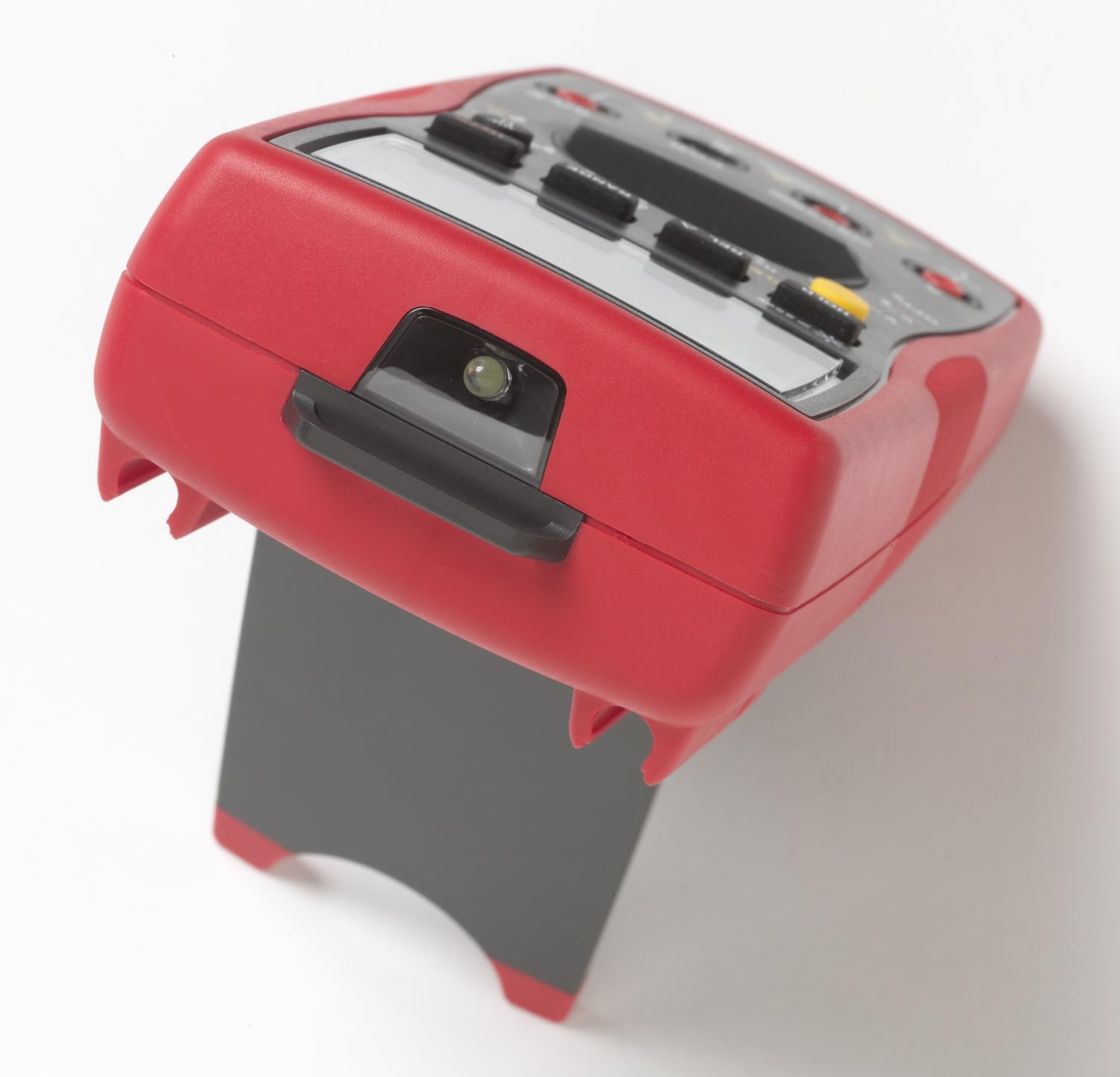
Image 5.1: The Amprobe AM-570 Digital Multimeter shown with its integrated kickstand extended, allowing for hands-free viewing during operation.
6. Operating Instructions
The AM-570 features a rotary dial for selecting primary measurement functions and push buttons for secondary functions and settings.
6.1 Function Selection
Turn the rotary dial to the desired measurement function. Use the SELECT button to toggle between primary and secondary functions within a single dial position (e.g., AC/DC voltage, resistance/continuity/diode).
6.2 Measurement Functions
- Voltage (V~ / V--): Select the V~ (AC) or V-- (DC) position. Connect test leads in parallel with the circuit.
- Current (10A / mAµA): Select the 10A or mAµA position. Connect the meter in series with the circuit. Ensure correct terminal connection.
- Resistance (Ω): Select the Ω position. Ensure power is off and capacitors are discharged. Connect test leads across the component.
- Continuity ())): Select the Ω position and press SELECT until the continuity symbol appears. A continuous beep indicates continuity.
- Diode Test (→|): Select the Ω position and press SELECT until the diode symbol appears. Connect leads across the diode.
- Capacitance (F): Select the F position. Ensure power is off and capacitors are discharged. Connect leads across the capacitor.
- Frequency (Hz) / Duty Cycle (%): Select the Hz% position. Connect leads to the signal source. Press SELECT to toggle between frequency and duty cycle.
- Temperature (°C/°F): Select the TEMP °C/°F position. Insert K-type thermocouple probes into the T1 and T2 inputs. Press SELECT to toggle between Celsius and Fahrenheit.
- Non-Contact Voltage (NCV): Select the NCV position. Hold the top of the meter near a live conductor. The NCV indicator and audible alarm will activate if voltage is detected.
- Low Z Mode: Select the LoZ V~ position for AC voltage measurements with low impedance. This helps to eliminate ghost voltages.
- Low Pass Filter: Activated automatically in certain AC voltage modes, this filter allows for accurate measurements on variable frequency drives.
6.3 Special Functions
- RANGE: Manually select the measurement range instead of auto-ranging.
- REL (Relative Mode): Measures the difference between a stored reference value and the current reading.
- MAX/MIN: Records the maximum and minimum values over a measurement period.
- HOLD: Freezes the current display reading.
- PEAK (1ms): Captures fast transient peaks (positive and negative) with a 1ms response time.

Image 6.1: An electrician utilizing the Amprobe AM-570 Digital Multimeter to perform voltage measurements within an industrial electrical panel, demonstrating practical application.
7. Maintenance
7.1 Cleaning
Wipe the meter with a damp cloth and mild detergent. Do not use abrasives or solvents. Ensure the meter is dry before use.
7.2 Battery Replacement
Refer to Section 5.1 for detailed instructions on replacing the 9V battery. Replace the battery promptly when the low battery indicator appears on the display.
7.3 Fuse Replacement
If the current measurement functions cease to operate, the internal fuses may need replacement. Fuse replacement should only be performed by qualified personnel. Refer to the full service manual for fuse specifications and replacement procedures. Always use fuses with the specified voltage and current ratings.
7.4 Storage
When not in use for extended periods, remove the battery to prevent leakage. Store the meter in a cool, dry environment, preferably in its carrying case.
8. Troubleshooting
| Problem | Possible Cause | Solution |
|---|---|---|
| Meter does not power on | Dead or incorrectly installed battery | Check battery polarity; replace battery (see Section 5.1). |
| No reading or "OL" (Overload) displayed | Incorrect function selected; open circuit; measurement range exceeded | Verify function switch position; check circuit continuity; select a higher range or auto-range. |
| Inaccurate readings | Low battery; dirty test leads/terminals; external interference | Replace battery; clean leads and terminals; move away from strong electromagnetic fields. |
| Current measurement not working | Blown fuse | Replace fuse (see Section 7.3). |
| NCV function inconsistent | Environmental factors; sensor position | Ensure direct proximity to live conductor; NCV is for indication only, use test leads for precise voltage verification. |
9. Specifications
| Parameter | Detail |
|---|---|
| Model | AM-570 |
| Manufacturer | Amprobe |
| Measurement Capabilities | AC/DC Voltage, AC/DC Current, Resistance, Frequency, Capacitance, Temperature, Duty Cycle |
| Safety Rating | CAT IV 600 V / CAT III 1000 V |
| True-RMS | Yes |
| Low Z Mode | Yes |
| Low Pass Filter | Yes |
| Power Source | 9V Battery |
| Product Dimensions | 4 x 10 x 2 inches (10.16 x 25.4 x 5.08 cm) |
| Item Weight | 13.05 ounces (370 grams) |
| Color | Black with Red overmolding |
10. Warranty and Support
Amprobe products are designed for reliability and performance. This product is covered by a manufacturer's warranty against defects in materials and workmanship. For specific warranty terms and conditions, please refer to the warranty card included with your product or visit the official Amprobe website.
For technical support, service, or replacement parts, please contact Amprobe customer service. Contact information can typically be found on the Amprobe website or in the product packaging.