1. Introduction
This manual provides detailed instructions for the REES52 Gy-521 MPU-6050 module, an integrated 3-axis gyroscope and 3-axis accelerometer. This module is designed for various applications requiring motion sensing and orientation data, offering precise 16-bit data output via the standard IIC communication protocol.
2. Features
- Integrated MPU-6050 chip for combined gyroscope and accelerometer functionality.
- Power supply: 3-5V (internal low dropout regulator).
- Communication modes: Standard IIC communications protocol.
- Built-in 16-bit AD converter for high-resolution 16-bit data output.
- Gyroscope range: ±250, 500, 1000, 2000 °/s.
- Acceleration range: ±2, 4, 8, 16g.
- Immersion Gold PCB machine welding process for enhanced quality.
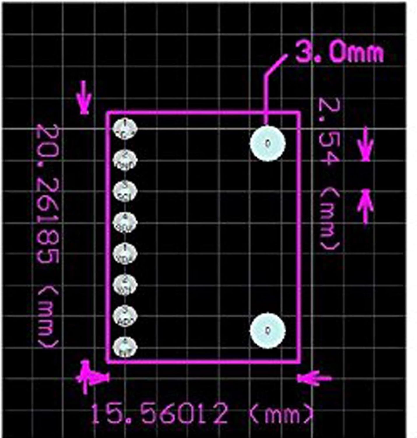
- Pin pitch: 2.54mm.
3. Setup
Proper connection and initialization are crucial for the Gy-521 MPU-6050 module. Ensure all connections are secure before applying power.
3.1. Pinout Overview
The module features several pins for power, ground, and IIC communication. Understanding the pin assignments is essential for correct wiring.


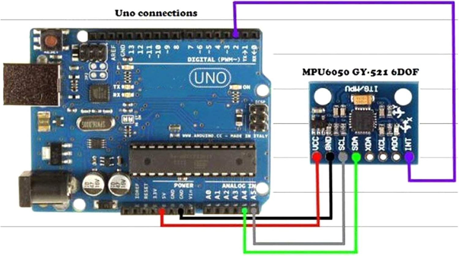
3.2. Wiring with Arduino Uno
For integration with an Arduino Uno, follow these connections:
- VCC on MPU-6050 to 5V on Arduino.
- GND on MPU-6050 to GND on Arduino.
- SCL on MPU-6050 to A5 on Arduino (SCL).
- SDA on MPU-6050 to A4 on Arduino (SDA).
- AD0 on MPU-6050 to GND on Arduino.
- INT on MPU-6050 to Digital Pin 2 on Arduino.
Note: SCL and SDA pins may vary between different Arduino board models. Consult your specific Arduino board's documentation for exact IIC pin locations.
3.3. Software Setup
To interface with the MPU-6050, you will need an appropriate library for your microcontroller. For Arduino, the I2Cdevlib is commonly used. This library provides functions to read raw accelerometer and gyroscope values, and can also calculate Euler angles, yaw, pitch, roll, world accelerations, and quaternions.
A video demonstrating the module and its data output is provided below:
4. Operation
Once the module is correctly wired and the necessary software library is installed, you can begin reading data. The MPU-6050 provides 16-bit digital output for both accelerometer and gyroscope data.
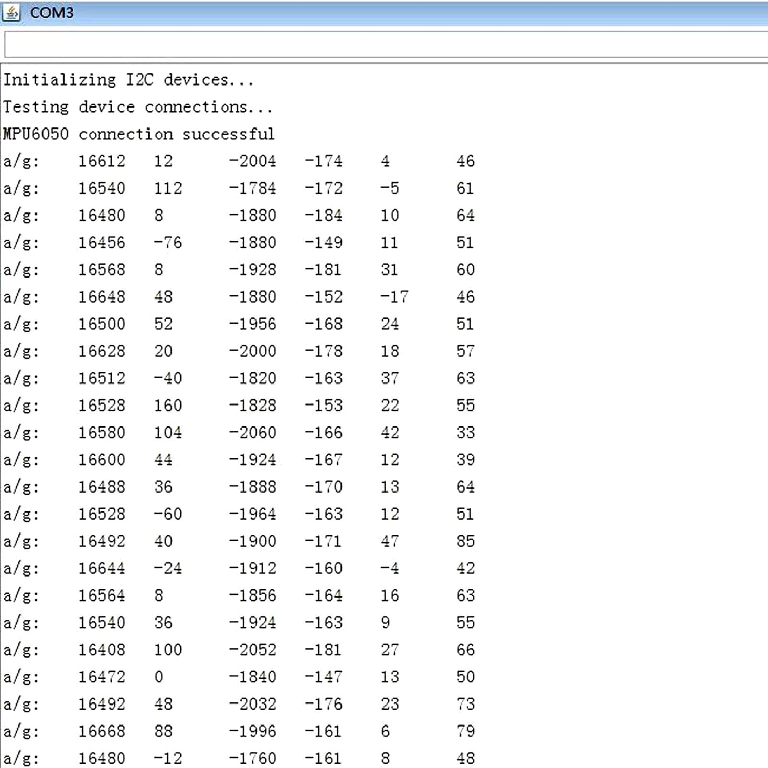
4.1. Data Output
The data can be read through the IIC interface and displayed on a serial monitor or used in your application. The output typically includes raw values for acceleration (X, Y, Z axes) and angular velocity (X, Y, Z axes).
4.2. Calibration
For accurate readings, especially for orientation and motion tracking, calibration of the accelerometer and gyroscope is recommended. This involves determining and applying offset values to compensate for sensor biases. Libraries like I2Cdevlib often include calibration routines or examples.
4.3. Applications
The MPU-6050 module is versatile and can be used in various applications, including:
- Motion sensing games.
- Reality enhancement systems.
- Electronic Image Stabilization (EIS).
- Optical Image Stabilization (OIS).
- Robotics and drone control.
- Wearable technology.

5. Specifications
| Specification | Value |
|---|---|
| Brand | REES52 |
| Item Model Number | REES-01 |
| Chip | MPU-6050 |
| Power Supply | 3-5V (DC) |
| Communication Protocol | Standard IIC |
| AD Converter | 16-bit |
| Data Output | 16-bit |
| Gyroscope Range | ±250, 500, 1000, 2000 °/s |
| Acceleration Range | ±2, 4, 8, 16g |
| Material | Silicon |
| Item Weight | 0.64 ounces (18.14 g) |
| Product Dimensions (LxWxH) | 1 x 1 x 1 inches |
| Pin Pitch | 2.54mm |
| Upper Temperature Rating | 85 Degrees Celsius |
6. Maintenance
To ensure the longevity and optimal performance of your REES52 Gy-521 MPU-6050 module, observe the following maintenance guidelines:
- Handle with Care: Avoid dropping or subjecting the module to excessive physical shock, as this can damage sensitive internal components.
- Keep Dry: Protect the module from moisture and humidity. Water can cause short circuits and corrosion.
- Avoid Static Discharge: Always handle the module in an anti-static environment or use proper grounding techniques to prevent electrostatic discharge (ESD) damage.
- Cleanliness: Keep the module free from dust and debris. Use a soft, dry brush or compressed air for cleaning.
- Proper Storage: When not in use, store the module in its original packaging or an anti-static bag in a cool, dry place.
7. Troubleshooting
If you encounter issues with your MPU-6050 module, consider the following troubleshooting steps:
- No Data Output:
- Verify all wiring connections are correct and secure, especially VCC, GND, SCL, and SDA.
- Ensure the module is receiving the correct power supply (3-5V).
- Check your code for proper IIC initialization and data reading functions.
- Confirm the IIC address of the MPU-6050 (default is 0x68, but can be 0x69 if AD0 is pulled high).
- Inaccurate Readings:
- Perform sensor calibration to account for biases and drifts. Many libraries provide calibration examples.
- Ensure the module is stable and not vibrating excessively during readings, unless that is the intended measurement.
- Check for electromagnetic interference from nearby components or power sources.
- Library Issues:
- Ensure you are using a compatible and up-to-date library for your development environment (e.g., I2Cdevlib for Arduino).
- Review library examples and documentation for correct usage.
8. Warranty and Support
This product is shipped new in package. For specific warranty details, please refer to the retailer's policy at the time of purchase. Technical support can often be found through online communities and forums dedicated to Arduino and MPU-6050 modules, where extensive resources and user-contributed solutions are available.
Shipping information: New in package, 3-5 day shipping. Ships from the USA.