
1. Introduction
The D-Link DGS-1500-28 SmartPro 24-Port Gigabit Switch is a high-performance Layer 3 managed switch designed for small to medium-sized businesses. It offers 24 Gigabit Ethernet ports and 4 SFP+ expansion slots, providing flexible connectivity and advanced management features. This manual provides essential information for the proper installation, configuration, operation, and maintenance of your DGS-1500-28 switch.
2. Package Contents
Verify the following items are present in your DGS-1500-28 package. If any item is missing or damaged, please contact your local D-Link reseller for assistance.
- DGS-1500-28 SmartPro 24-Port Gigabit Switch
- Power Cord
- Rack Mount Kit (two brackets and screws)
- Rubber Feet (for desktop installation)
- Console Cable (RJ-45 to RS-232)
- Quick Installation Guide
- CD-ROM (containing product documentation)
3. Physical Description
3.1 Front Panel
The front panel of the DGS-1500-28 switch features the Gigabit Ethernet ports, SFP+ slots, and LED indicators for monitoring the switch's status and activity.
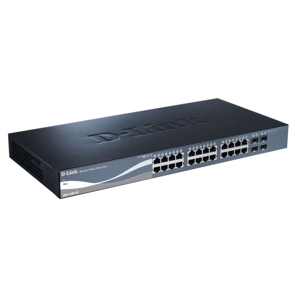
This image displays the front panel of the D-Link DGS-1500-28 switch, featuring 24 RJ-45 Gigabit Ethernet ports and LED indicators for status and activity.
- RJ-45 Ports (1-24): 10/100/1000 Mbps Gigabit Ethernet ports for connecting network devices.
- SFP+ Slots (25-28): 10 Gigabit Ethernet SFP+ ports for fiber optic connections or stacking.
- LED Indicators:
- Power LED: Indicates power status.
- Link/Act LED (per port): Indicates network link and data activity.
- Speed LED (per port): Indicates connection speed (e.g., green for Gigabit, amber for 10/100 Mbps).
3.2 Rear Panel
The rear panel typically includes the power connector, grounding screw, and a console port for out-of-band management.
- AC Power Receptacle: Connects to the provided AC power cord.
- Grounding Screw: Provides an optional connection for grounding the switch.
- Console Port: RJ-45 port for connecting a console cable to a computer for command-line interface (CLI) management.
4. Installation
4.1 Desktop Installation
- Attach the four rubber feet to the recessed areas on the bottom of the switch.
- Place the switch on a sturdy, level surface that can support its weight.
- Ensure adequate ventilation around the switch.
4.2 Rack Installation
- Attach the two rack-mounting brackets to the sides of the switch using the provided screws.
- Secure the switch into a standard 19-inch equipment rack using appropriate rack screws (not included).
- Ensure proper airflow and avoid placing the switch near heat sources.
4.3 Powering On the Switch
- Connect the AC power cord to the power receptacle on the rear panel of the switch.
- Plug the other end of the power cord into a suitable power outlet.
- The Power LED on the front panel will illuminate, indicating the switch is receiving power.
5. Initial Configuration
The DGS-1500-28 switch can be managed via a web-based graphical user interface (GUI) or a command-line interface (CLI) through the console port.
5.1 Accessing the Web-based Management Interface
- Connect a computer to any of the switch's RJ-45 ports using an Ethernet cable.
- Configure your computer's IP address to be in the same subnet as the switch's default IP address (e.g., if the switch is 10.90.90.90, set your computer to 10.90.90.100).
- Open a web browser and enter the switch's default IP address (e.g., http://10.90.90.90) in the address bar.
- Enter the default username and password (refer to the Quick Installation Guide for default credentials).
- Upon successful login, you will access the switch's web management interface.
Note: It is highly recommended to change the default password immediately after initial login for security purposes.
6. Operating the Switch
Once configured, the DGS-1500-28 operates as a network switch, forwarding data between connected devices. The LED indicators provide visual feedback on the operational status of the switch and its ports.
6.1 Port Functionality
- RJ-45 Ports: Automatically detect the speed and duplex mode of connected devices (10/100/1000 Mbps).
- SFP+ Slots: Support 10 Gigabit Ethernet transceivers for high-speed uplinks or stacking. Ensure compatible SFP+ modules are used.
6.2 Advanced Features
The DGS-1500-28 series integrates advanced features to enhance network performance and management:
- Virtual Stacking: Allows up to 32 DGS-1500 series devices to be managed as a single unit with one IP address, simplifying network administration and scalability.
- Layer 3 Static Routing: Enables the switch to forward IP packets between different IP subnets based on static routes configured by the administrator. This feature is crucial for inter-VLAN routing and basic network segmentation.
7. Maintenance
Regular maintenance ensures optimal performance and longevity of your DGS-1500-28 switch.
- Firmware Updates: Periodically check the D-Link support website for the latest firmware versions. Updating firmware can provide new features, performance improvements, and security patches.
- Environmental Conditions: Ensure the switch operates within recommended temperature and humidity ranges. Keep ventilation openings clear of obstructions.
- Cleaning: Use a soft, dry cloth to clean the exterior of the switch. Do not use liquid or aerosol cleaners.
- Configuration Backup: Regularly back up your switch configuration to an external device. This allows for quick restoration in case of a factory reset or device replacement.
8. Troubleshooting
This section provides solutions to common issues you might encounter with your DGS-1500-28 switch.
8.1 Power LED is Off
- Ensure the power cord is securely connected to both the switch and a working power outlet.
- Verify the power outlet is functional by plugging in another device.
8.2 No Link/Activity on a Port
- Check the Ethernet cable connection at both ends. Try a different cable.
- Ensure the connected device is powered on and functioning correctly.
- Verify the port status in the switch's web management interface.
- For SFP+ ports, ensure the SFP+ module is correctly inserted and compatible.
8.3 Cannot Access Web Management Interface
- Confirm your computer's IP address is in the same subnet as the switch's IP address.
- Verify the switch's IP address. If unknown, you may need to reset the switch to factory defaults (refer to the Quick Installation Guide for reset procedures).
- Ensure there are no IP address conflicts on the network.
- Try accessing the interface from a different web browser or computer.
9. Specifications
| Feature | Description |
|---|---|
| Brand | D-Link |
| Model Number | DGS150028 |
| Ports | 24 x 10/100/1000 Mbps RJ-45 Gigabit Ports, 4 x 10 Gigabit SFP+ Expansion Slots |
| Interface Type | RJ45, SFP+ |
| Switching Capacity | Up to 128 Gbps (non-blocking) |
| Layer Support | Layer 3 (Static Routing) |
| Management | Web-based GUI, CLI, SNMP |
| Compatible Devices | Desktop, Rack-mount devices |
| Item Weight | 0.01 Ounces (Note: This value may be a placeholder or incorrect. Refer to product packaging for accurate weight.) |
| UPC | 790069362927 |
| ASIN | B007TL1DHM |
10. Warranty and Support
D-Link products are backed by a limited warranty. The specific terms and conditions of the warranty may vary by region and product. Please refer to the warranty information included with your product or visit the official D-Link website for detailed warranty statements.
For technical support, product documentation, firmware updates, and FAQs, please visit the D-Link support website: www.dlink.com/support
You may also contact D-Link technical support directly through the contact information provided on their website for your specific region.


