Introduction
This manual provides detailed instructions for the installation, operation, and maintenance of the Sure Electronics AA-AB32231 2x8W at 4 Ohm TPA3110 Class-D Audio Amplifier Board. This compact and efficient amplifier board is designed for various audio applications requiring reliable stereo amplification.
Product Features
- Output Power: 2 x 8 Watts at 4 Ohm
- Amplifier Type: Class-D (TPA3110 chip)
- Power Supply: DC 8V to 19V (recommended 12V-16V)
- Channels: 2.0 Stereo
- Input Options: 3.5mm audio jack or solder terminals
- Compact Design: Ideal for embedded audio projects
Safety Information
Please read and understand the following safety precautions before operating the amplifier board:
- Ensure the power supply voltage is within the specified range (DC 8V-19V). Exceeding this range can damage the board.
- Disconnect power before making any connections or disconnections.
- Avoid short-circuiting speaker outputs or power supply terminals.
- Do not expose the board to moisture, extreme temperatures, or static electricity.
- Handle the board by its edges to prevent damage to components.
- This product is intended for experienced users familiar with electronic components and wiring.
Setup and Connections
Refer to the images below for visual guidance on connecting the amplifier board.

Figure 1: Top view of the AA-AB32231 amplifier board.
This image displays the top side of the amplifier board, highlighting the various connection points. On the left, you can see the DC power input terminals (GND and VCC). The audio input jack is visible on the top left, and speaker output terminals (OUT1+, OUT1-, OUT2+, OUT2-) are located on the top and right sides of the board.
1. Power Supply Connection
- Connect a DC power supply (8V to 19V) to the "DC IN 8-19V" terminals (J1) on the left side of the board.
- Ensure correct polarity: connect the positive (+) terminal of the power supply to VCC and the negative (-) terminal to GND.
- A 12V or 16V power supply is generally recommended for optimal performance. Note that some 9V power supplies may not provide sufficient voltage for proper operation.
2. Audio Input Connection
- The board offers two audio input methods:
- 3.5mm Audio Jack (J3): Connect your audio source (e.g., smartphone, MP3 player, computer) directly to the 3.5mm stereo input jack.
- Solder Terminals (J2): For custom installations, audio input can be wired directly to the "GND", "IN1", and "IN2" solder pads.
3. Speaker Output Connection
- Connect your speakers to the "OUT1" and "OUT2" terminals.
- For Channel 1 (OUT1): Connect the positive (+) terminal of the speaker to OUT1+ and the negative (-) terminal to OUT1-.
- For Channel 2 (OUT2): Connect the positive (+) terminal of the speaker to OUT2+ and the negative (-) terminal to OUT2-.
- Ensure speakers have an impedance of 4 Ohms for optimal 8W output.
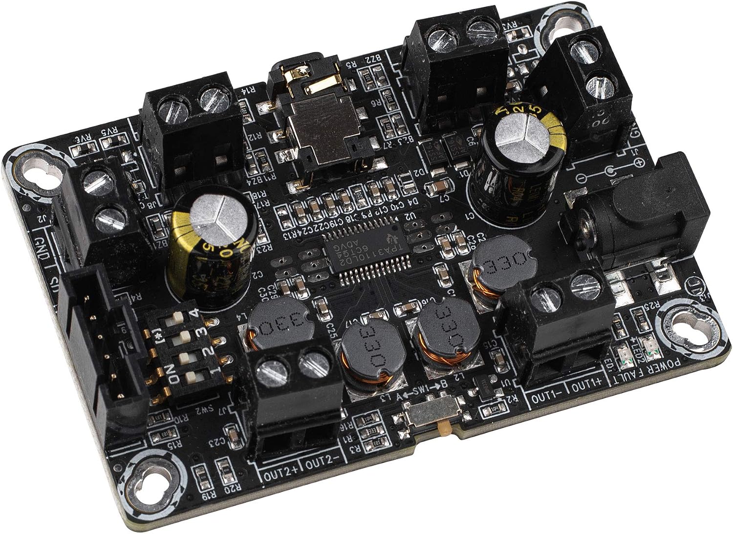
Figure 2: Angled view of the AA-AB32231 amplifier board.
This angled view provides a clearer perspective of the screw terminals for speaker outputs and power input, as well as the 3.5mm audio input jack. It also illustrates the compact form factor of the amplifier board.
4. Mode Selection (Mono/Stereo, BTL/PBTL)
The board features switches on the underside for configuring the output mode. Refer to Figure 3 for switch locations.

Figure 3: Bottom view of the AA-AB32231 amplifier board with mode switches.
This image shows the underside of the amplifier board, where SW1 and SW2 are located. These switches control the operating mode, allowing selection between stereo (DIFF/SE) and mono (BTL/PBTL) configurations. The labels indicate the specific settings for each switch position.
- SW1 (MODE): Selects between BTL (Bridge-Tied Load) and PBTL (Parallel Bridge-Tied Load) modes.
- SW2 (MODE): Configures the input and output differential/single-ended modes. The combination of SW1 and SW2 determines the final operating mode (e.g., stereo differential input, mono BTL output).
- Consult the markings on the board for specific switch positions corresponding to desired modes (e.g., "SHORT IN MONO MODE" for mono input).
- Ensure the board is powered off before changing switch settings.
Operating Instructions
- After all connections (power, audio input, speakers) are securely made, apply power to the board.
- The power indicator LED (if present) should illuminate.
- Start playing audio from your source device.
- Adjust the volume using your audio source device. This amplifier board typically operates at a fixed gain.
- If no sound is heard, refer to the Troubleshooting section.
Specifications
| Feature | Specification |
|---|---|
| Model | AA-AB32231 |
| Amplifier Chip | TPA3110 |
| Output Power | 2 x 8W @ 4 Ohm |
| Power Supply Voltage | DC 8V - 19V |
| Number of Channels | 2 (Stereo) |
| Dimensions (L x W x H) | 3.58 x 2.68 x 0.59 inches (approx. 91 x 68 x 15 mm) |
| Item Weight | 1.76 ounces (approx. 50 grams) |
| Mounting Type | Surface Mount |
Troubleshooting
- No Sound:
- Check power supply connections and ensure the power LED is on.
- Verify audio input cable is securely connected to both the source and the amplifier board.
- Ensure speaker wires are correctly connected to the output terminals and not short-circuited.
- Confirm the audio source is playing and its volume is turned up.
- Check the mode switches (SW1, SW2) on the underside of the board to ensure they are set for the desired stereo or mono operation.
- Distorted Sound:
- Reduce the volume from the audio source. Overdriving the input can cause distortion.
- Ensure the power supply is stable and provides sufficient current.
- Verify speaker impedance matches the amplifier's requirements (4 Ohms recommended).
- Intermittent Sound or Muting:
- Some power supplies, particularly 9V, may not provide stable operation. Try a 12V or 16V power supply.
- Check for loose connections on power, input, or output terminals.
- Ensure the board is not overheating. Provide adequate ventilation if enclosed.
Maintenance
The Sure Electronics AA-AB32231 amplifier board requires minimal maintenance:
- Keep the board clean and free from dust and debris. Use a soft, dry brush or compressed air for cleaning.
- Avoid touching the electronic components directly, especially when powered.
- Store the board in a dry, cool environment when not in use.
- Regularly check connections for tightness and corrosion.
Warranty and Support
For warranty information and technical support, please refer to the documentation provided at the point of purchase or contact Sure Electronics directly through their official website. Keep your purchase receipt as proof of purchase.