1. Introduction
This manual provides comprehensive instructions for the installation, operation, and maintenance of your Telewave ANT150D Single Folded Dipole Antenna. Designed for robust performance, this antenna covers the 138 – 174 MHz frequency range, making it suitable for various communication applications.
Key features include:
- Frequency Range: 138 – 174 MHz
- Gain: 1 – 2.5 dBd (dependent on pattern)
- Maximum Power Input: 500 W
- Precision phasing harness for optimum performance
- Terminated with an N Male connector
2. Setup and Installation
Proper installation is crucial for optimal antenna performance and longevity. Please follow these steps carefully.
2.1 Unpacking and Inspection
Carefully unpack all components and inspect for any signs of shipping damage. Retain all packaging materials for future use or in case of return.
Included components:
- Telewave ANT150D Dipole Antenna
- Clamp Set for mast mounting
Note: A mast for mounting the antenna must be purchased separately.
2.2 Mounting the Antenna
The ANT150D antenna is designed for mast mounting using the included clamp set. Ensure the mast is sturdy and capable of supporting the antenna's weight and wind load.
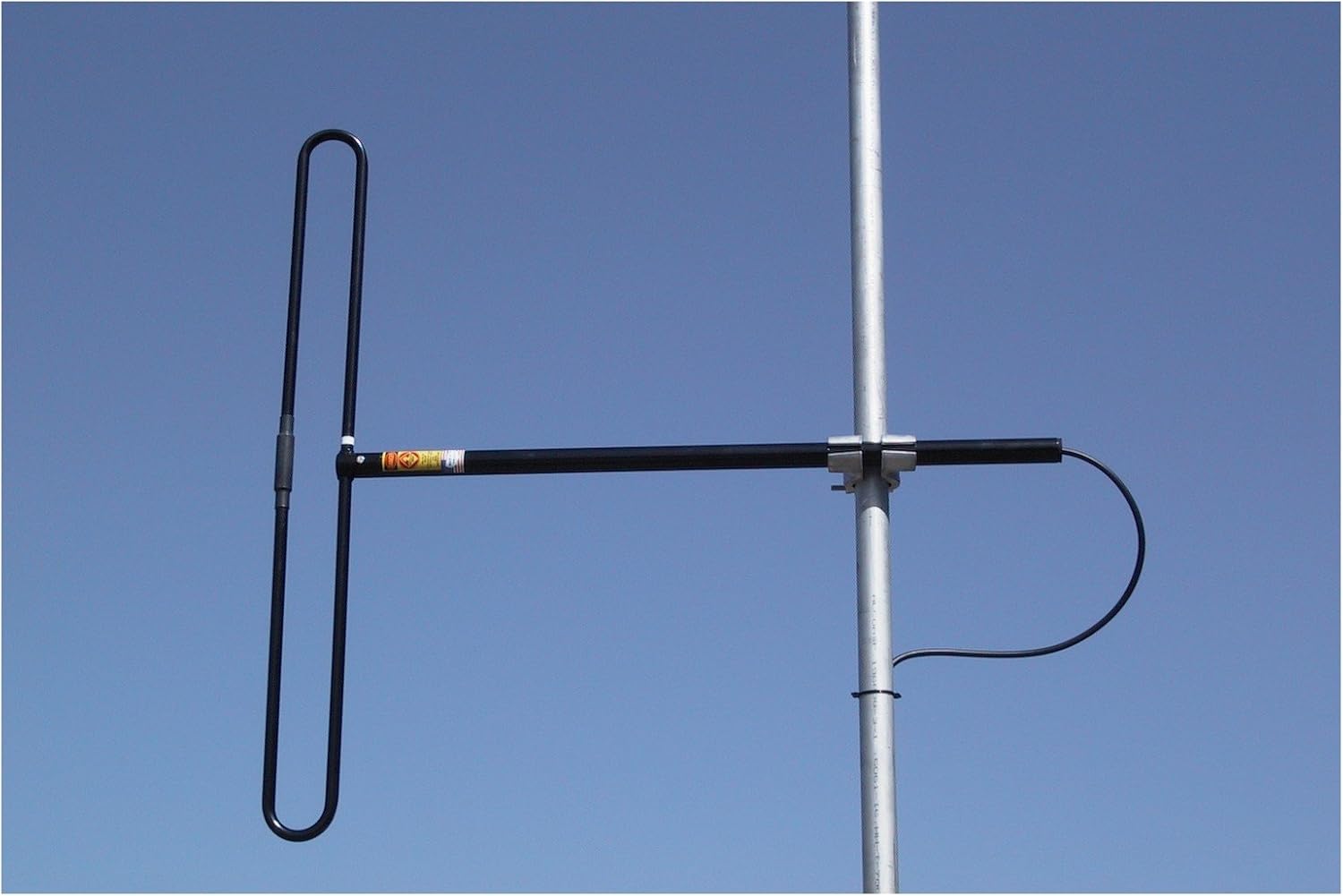
Figure 1: Telewave ANT150D Dipole Antenna properly mounted on a mast.
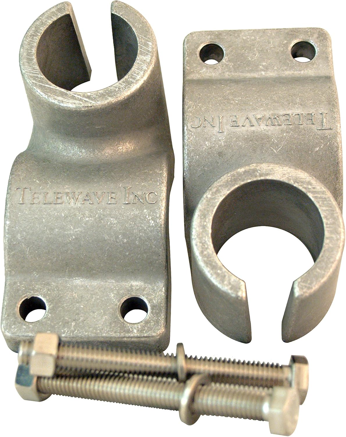
Figure 2: The included clamp set for securing the antenna to a mast.
- Attach the clamp set to the antenna's mounting bracket.
- Position the antenna on the desired mast location.
- Securely tighten the clamp set bolts to firmly attach the antenna to the mast. Ensure the antenna is vertical and stable.
2.3 Coaxial Cable Connection
The ANT150D antenna is terminated with an N Male connector. You will need a coaxial cable with an N Female connector to connect the antenna to your radio equipment.
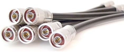
Figure 3: Example of N-type coaxial connectors for antenna connection.
- Connect the N Female end of your coaxial cable to the N Male connector on the antenna.
- Ensure the connection is hand-tightened securely to prevent moisture ingress and ensure good signal transfer. Do not overtighten.
- Route the coaxial cable away from sharp edges and secure it along the mast using appropriate cable ties or clamps to prevent strain and damage.
3. Operating Instructions
The Telewave ANT150D is a passive antenna and does not require external power. Its operation is dependent on proper installation and connection to compatible radio equipment.
- Frequency Compatibility: Ensure your transmitting and receiving equipment operates within the antenna's specified frequency range of 138 – 174 MHz.
- Power Handling: Do not exceed the maximum power input of 500 W to prevent damage to the antenna.
- SWR Check: After installation, it is recommended to check the Standing Wave Ratio (SWR) using an SWR meter to ensure optimal performance and a good match between the antenna and your radio system. An SWR close to 1:1 indicates efficient power transfer.
- Environmental Considerations: While designed for outdoor use, extreme weather conditions (e.g., severe ice buildup, strong winds beyond design limits) can affect performance or cause damage.
4. Maintenance
The ANT150D antenna is designed for minimal maintenance. However, periodic checks can help ensure long-term reliability and performance.
- Visual Inspection: Annually inspect the antenna, mast, and coaxial cable for any signs of physical damage, corrosion, or loose connections.
- Connection Integrity: Check the coaxial cable connection at the antenna for tightness and signs of moisture ingress. Apply dielectric grease to connections if operating in high-humidity environments.
- Mounting Hardware: Verify that all mounting bolts and clamps are secure. Tighten if necessary.
- Cleaning: If the antenna becomes excessively dirty, gently clean it with a soft cloth and mild soap and water. Rinse thoroughly with clean water and allow to air dry. Do not use abrasive cleaners or solvents.
5. Troubleshooting
If you experience issues with your antenna, consider the following common troubleshooting steps:
| Problem | Possible Cause | Solution |
|---|---|---|
| Poor Signal Reception/Transmission | Loose or corroded coaxial cable connection. Incorrect frequency setting on radio. Damaged coaxial cable. Antenna not properly aimed (if applicable, though less critical for dipole). | Check and tighten all connections. Verify radio frequency. Inspect cable for damage and replace if necessary. Ensure antenna is mounted vertically and clear of obstructions. |
| High SWR Reading | Faulty coaxial cable or connectors. Antenna damage. Incorrect antenna tuning (not applicable for fixed dipole). Proximity to metal objects. | Inspect and test coaxial cable and connectors. Visually inspect antenna for damage. Ensure antenna is clear of large metallic structures. |
| Antenna Instability | Loose mounting clamps. Insufficiently sturdy mast. | Retighten mounting clamps. Ensure mast is appropriate for antenna size and weight, and properly secured. |
6. Specifications
| Attribute | Value |
|---|---|
| Model Number | ANT150D |
| Brand | Telewave |
| Frequency Range | 138 – 174 MHz |
| Antenna Type | Single Folded Dipole |
| Gain | 1 – 2.5 dBd |
| Maximum Power Input | 500 W |
| Connector Type | N Male |
| Item Weight | 6 pounds (2.72 kg) |
| Package Dimensions | 46 x 8 x 4 inches (116.8 x 20.3 x 10.2 cm) |
| UPC | 729198675271 |
7. Warranty and Support
For warranty information and technical support, please contact Telewave directly or refer to their official website. Keep your purchase receipt as proof of purchase.
Manufacturer: Telewave