1. Introduction
The DATA COMM In-Wall Cable Management Kit with Duplex Surge Suppressor provides a clean and safe solution for concealing power and low-voltage cables behind wall-mounted televisions and other electronic devices. This kit allows for the relocation of power outlets and the routing of various cables, such as HDMI, LAN, and audio/video cables, within the wall cavity, eliminating visible cable clutter and enhancing the aesthetic of your living space. The integrated duplex surge suppressor offers protection for connected electronics.
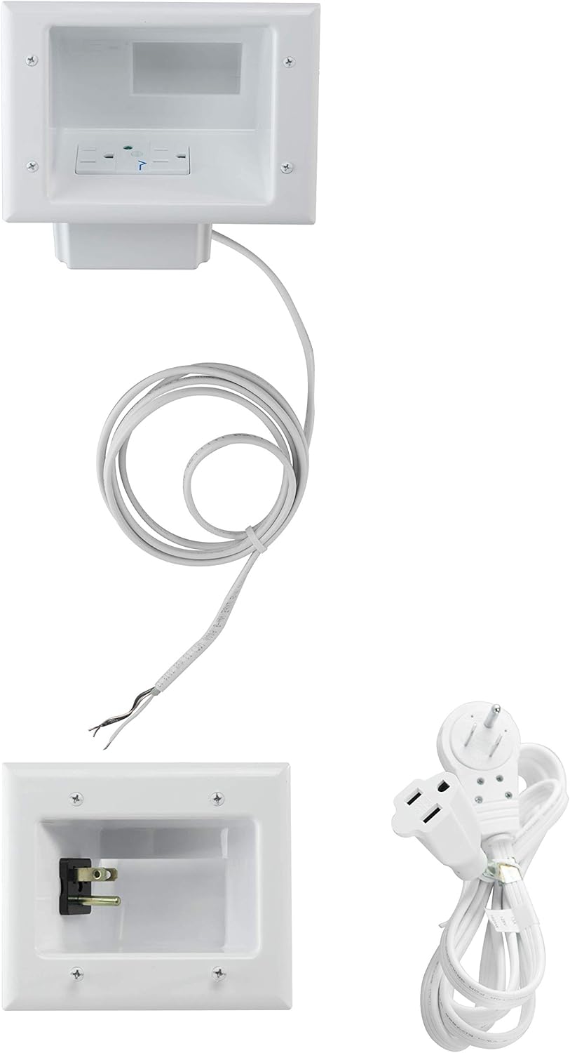
Figure 1.1: Overview of the In-Wall Cable Management Kit components, including the top power receptacle, bottom power inlet, and extension cord.
2. Key Features
- Low Profile Design: Engineered to fit seamlessly behind the thinnest TV mounts and televisions, ensuring a flush installation.
- Integrated Duplex Surge Suppressor: Features a 15 Amp / 125 Volt tamper-resistant duplex receptacle with built-in surge protection, allowing safe power installation behind wall-mounted devices.
- Secure Mounting: Equipped with metal mounting wings on both top and bottom plates that fasten securely against the drywall upon tightening, providing a stable and flush finish.
- Recessed Power Inlet: The female end of the included extension cord recesses completely into the wall when plugged into the straight blade inlet, maintaining a clean appearance.
- 360° Rotating Flat Head Plug: The male end of the extension cord features a 360° rotating flat head, enabling furniture to be placed flush against the wall without obstruction.
- Wide Cable Pass-Through: Designed with extra-wide recessed grooves to accommodate multiple low-voltage cables (e.g., HDMI, LAN, audio/video) simultaneously.

Figure 2.1: The low-profile design ensures the kit fits discreetly behind thin TV mounts and televisions.

Figure 2.2: The kit's components laid out, demonstrating the capacity for multiple low-voltage cables.

Figure 2.3: Detail of the metal mounting wings that secure the plates to the drywall.

Figure 2.4: Illustration of the kit's compatibility with various wall types up to 1 inch thick, including drywall, paneling, stucco, plaster, and tile.
3. Setup and Installation
3.1. Before You Begin
Before starting the installation, ensure you have all necessary tools and understand the process. Safety is paramount when working with electrical components and within walls. It is recommended to turn off power to the circuit at the breaker before beginning any electrical work.
- Tools Required: Pencil, Level, Drywall Saw (or utility knife), Stud Finder, Measuring Tape, Screwdriver (Phillips head), Electrical Tape (optional).
- Safety Precautions: Always turn off power at the circuit breaker before cutting into walls or handling electrical wiring. Verify no live wires are present using a non-contact voltage tester. Be aware of fire blocks and studs within the wall cavity.
3.2. Installation Steps
Follow these steps for a successful installation:
- Plan Placement: Determine the ideal locations for the top and bottom recessed plates. The top plate should be behind your TV, and the bottom plate near an existing power outlet, typically closer to the floor. Ensure both locations are between wall studs and clear of any obstructions like pipes or existing wiring.
- Mark and Cut Openings: Use the provided templates to mark the precise cutouts for both the top and bottom plates on your drywall. Use a level to ensure markings are straight. Carefully cut out the marked sections using a drywall saw.
- Install Top Plate: Insert the top recessed plate (with the pre-wired duplex surge suppressor) into its cutout. Ensure the electrical wiring for the surge suppressor is accessible. Tighten the metal mounting wings by turning the screws on the faceplate until the wings firmly secure the plate against the drywall.
- Route Electrical Cable: Feed the included electrical cable from the top plate down through the wall cavity to the bottom cutout. If necessary, use a fish tape or weighted string to guide the cable.
- Route Low-Voltage Cables: Feed your low-voltage cables (e.g., HDMI, Ethernet, audio) from the TV location through the top plate's cable pass-through and down to the bottom cutout. Ensure enough slack is left at both ends for connections.
- Install Bottom Plate: Connect the electrical cable from the top plate to the bottom recessed plate's straight blade power inlet. Insert the bottom plate into its cutout. Tighten the metal mounting wings to secure the plate firmly against the drywall.
- Connect Power: Plug the female end of the included extension cord into the recessed power inlet on the bottom plate. Plug the male end of the extension cord (with the 360° rotating flat head) into your existing wall power outlet.
- Connect Devices: Plug your TV's power cord into the duplex surge suppressor on the top plate. Connect your low-voltage cables to your TV and other devices as needed.

Figure 3.1: The kit's components ready for installation, showing the top and bottom units and the power cord.

Figure 3.2: Visual guide demonstrating key installation steps, including cutting the wall, inserting units, and routing cables.
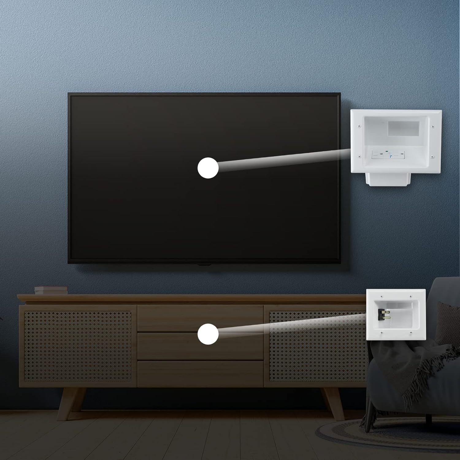
Figure 3.3: A visual comparison showing the transformation from messy, visible cables to a clean, concealed setup.

Figure 3.4: Conceptual diagram showing how power and low-voltage cables are routed from the TV behind the wall to the lower power inlet.
4. Operating Instructions
Once installed, the DATA COMM In-Wall Cable Management Kit operates passively, providing power and cable pass-through functionality.
4.1. Power Outlets
The top recessed plate provides a standard 15 Amp / 125 Volt duplex electrical outlet. Plug your television and other compatible devices directly into these outlets. The bottom recessed plate serves as the power inlet for the system, connecting to your existing wall outlet via the provided extension cord.
4.2. Cable Pass-Through
The wide openings on both the top and bottom plates allow for the passage of multiple low-voltage cables. Simply feed your HDMI, optical audio, Ethernet, or other data cables through these openings to conceal them within the wall.
4.3. Surge Protection
The integrated surge suppressor in the top plate protects connected devices from power surges and spikes. In the event of a significant surge, the suppressor is designed to absorb excess voltage, safeguarding your valuable electronics. There is typically an indicator light on the receptacle to show if the surge protection is active. If this light is off, the surge protection may be compromised, and the unit should be inspected or replaced.
5. Maintenance
The DATA COMM In-Wall Cable Management Kit requires minimal maintenance. Regular inspection can help ensure continued safe operation.
- Cleaning: Periodically wipe the visible faceplates with a soft, dry cloth to remove dust. Do not use abrasive cleaners or solvents.
- Inspection: Annually inspect the visible components for any signs of damage, loose connections, or discoloration. Check the surge protection indicator light on the top receptacle to ensure it is active.
- Cable Management: Ensure cables routed through the pass-through are not excessively strained or pinched.
6. Troubleshooting
This section addresses common issues you might encounter with your cable management kit.
| Problem | Possible Cause | Solution |
|---|---|---|
| No power from top receptacle. |
|
|
| Cables do not fit through pass-through. |
|
|
| Unit feels loose in the wall. |
|
|
7. Specifications
| Attribute | Detail |
|---|---|
| Model Number | 50-8823-WH-KIT |
| Product Dimensions | 8.5 x 7 x 2.75 inches |
| Item Weight | 2.45 pounds |
| Electrical Rating (Top Receptacle) | 15 Amp / 125 Volt |
| Surge Protection | Integrated Duplex Surge Suppressor |
| Wall Thickness Compatibility | Up to 1 inch (Drywall, Paneling, Stucco, Plaster, Tile, etc.) |
| Color | White |
| Indoor/Outdoor Usage | Indoor |
8. Warranty and Support
For information regarding warranty coverage, technical support, or replacement parts for your DATA COMM In-Wall Cable Management Kit, please contact DATA COMM customer service directly. Refer to the product packaging or the official DATA COMM website for the most current contact details and warranty terms.
Manufacturer: Ingram Micro CE
Brand: DATA COMM
Note: No official product videos from the seller were found in the provided data to embed in this manual.