Square D 9013FHG12J52M1X
Square D Pumptrol Pressure Switch 9013FHG12J52M1X Instruction Manual
Model: 9013FHG12J52M1X | Brand: Square D
1. Introduction
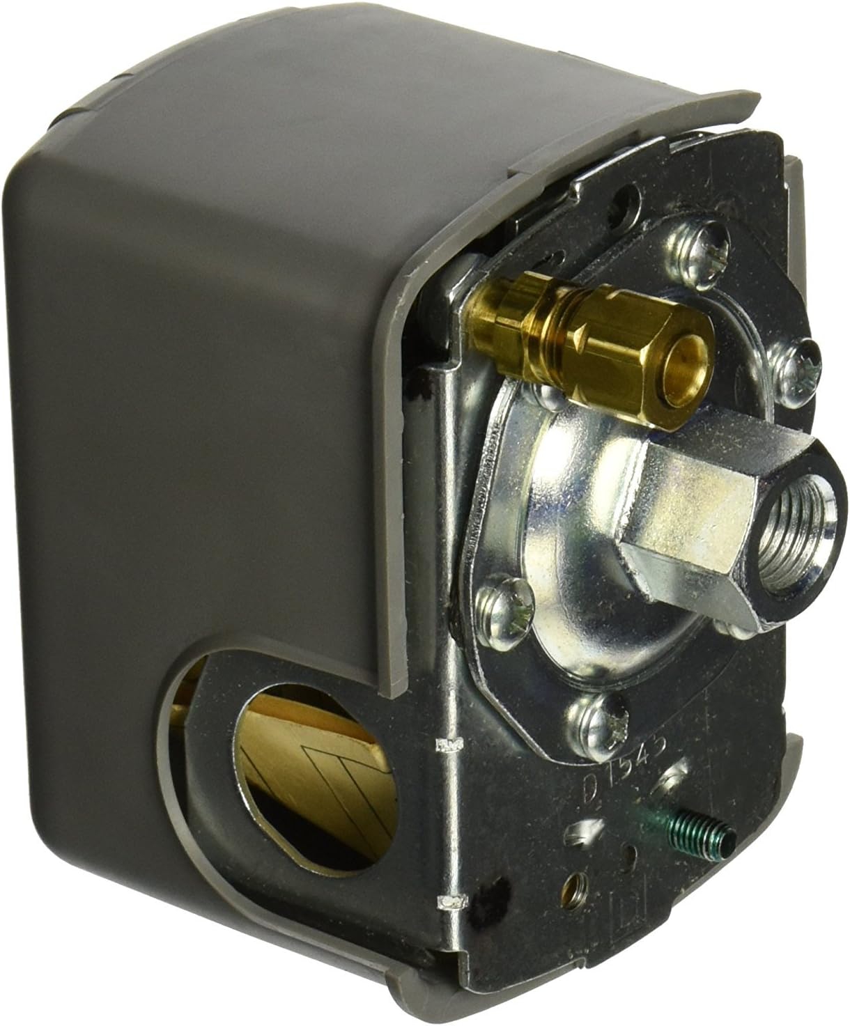
This document provides comprehensive instructions for the installation, operation, and maintenance of the Square D Pumptrol Pressure Switch, model 9013FHG12J52M1X. This electromechanical pressure switch is designed for controlling small electrically driven air compressors. It features a factory-set pressure range of 95-125 psi, an integrated unloader valve, and a convenient On/Off lever for manual control.
2. Safety Information
Read and understand all instructions before installing or operating this device. Failure to follow these instructions may result in property damage, serious injury, or death.
- Electrical Hazard: Disconnect all power to the compressor and pressure switch before performing any installation, maintenance, or troubleshooting. Electrical shock can cause severe injury or death.
- Pressure Hazard: Depressurize the air system completely before working on the pressure switch or any connected components. Sudden release of compressed air can cause injury.
- Qualified Personnel: Installation and wiring should only be performed by qualified electricians or service technicians in accordance with all local and national electrical codes.
- Proper Application: Use this pressure switch only for its intended purpose: controlling small electrically driven air compressors within the specified pressure and electrical ratings.
- Environmental Conditions: Ensure the operating environment is within the specified temperature range (-22 to 257 °F for controlled fluid air) and free from excessive moisture or corrosive elements.
3. Product Overview
The Square D Pumptrol Pressure Switch 9013FHG12J52M1X is an electromechanical device that monitors air pressure in a compressor system and activates or deactivates the compressor motor based on preset pressure thresholds. It includes an unloader valve and an On/Off lever for operational control.


4. Setup and Installation
Proper installation is critical for the safe and efficient operation of the pressure switch.
4.1 Mounting
- The pressure switch can be mounted in any position.
- Ensure the mounting location is stable, free from excessive vibration, and allows for easy access for wiring and maintenance.
4.2 Fluid Connection
- Connect the pressure switch to the air compressor system using the 0.25 inch NPSF internal fluid connection.
- Use appropriate thread sealant to ensure an airtight connection.
- Verify that the connection is secure and free of leaks before applying pressure.
4.3 Electrical Connection
WARNING: Ensure all power is disconnected before wiring.
- The switch features screw-clamp terminals suitable for up to 10 AWG wire (5.261 mm² clamping capacity).
- The contact type is 2 NC (Normally Closed), snap action, DPST-DB (Double Pole, Single Throw, Double Break), Form YY.
- Connect the power circuit wires to the appropriate terminals (L1-T1, L2-T2). Refer to the wiring diagram provided with your compressor or consult a qualified electrician.
- Ensure proper grounding by connecting the ground wire to the designated ground screw.
- Provide short circuit protection with a 20 A cartridge fuse, type gG.
- The switch has two 0.88 inch cable entries with 0.84 inch across flats, conforming to UL 508.
4.4 Pressure Adjustment (Factory Set)
This model is factory set to turn off at 125 psi. The adjustable range on rising pressure is 70-150 psi, with an approximate adjustable differential of 30 psi. Adjustments should only be made by qualified personnel using appropriate tools and a calibrated pressure gauge.
5. Operating Instructions
The pressure switch controls the compressor automatically based on the pressure settings. The On/Off lever provides manual control.