1. Introduction
The ART Pro Channel II is a professional tube-based signal processing unit designed for studio and live sound applications. It integrates a high-quality microphone preamp, a versatile compressor, and a powerful equalizer into a single, compact chassis. This unit is engineered to provide warm, smooth, and silky sound quality, enhancing your audio recordings and live performances.
This manual provides detailed instructions for the setup, operation, and maintenance of your ART Pro Channel II to ensure optimal performance and longevity.
2. Key Features
- Professional Tube-Based Microphone/Line Recording Channel.
- Three independent World-Class modules: tube mic preamplifier, switchable optical/tube compressor, and tube equalizer.
- Warm, Smooth, and Silky Sound Quality.
- Precision Detented Potentiometers for accurate settings.
- Selectable VU Metering (mic pre out, compressor out, or Main Out).
3. Setup
3.1 Unpacking and Inspection
Carefully remove the Pro Channel II from its packaging. Inspect the unit for any signs of damage that may have occurred during shipping. If damage is found, contact your dealer immediately.
3.2 Front Panel Overview

Figure 3.2.1: Front Panel of the ART Pro Channel II. This view displays the input gain, low-cut filter, preamp controls, compressor section with threshold, ratio, attack, release, and output controls, the four-band parametric equalizer, and the master output section with VU metering.
3.3 Rear Panel Connections
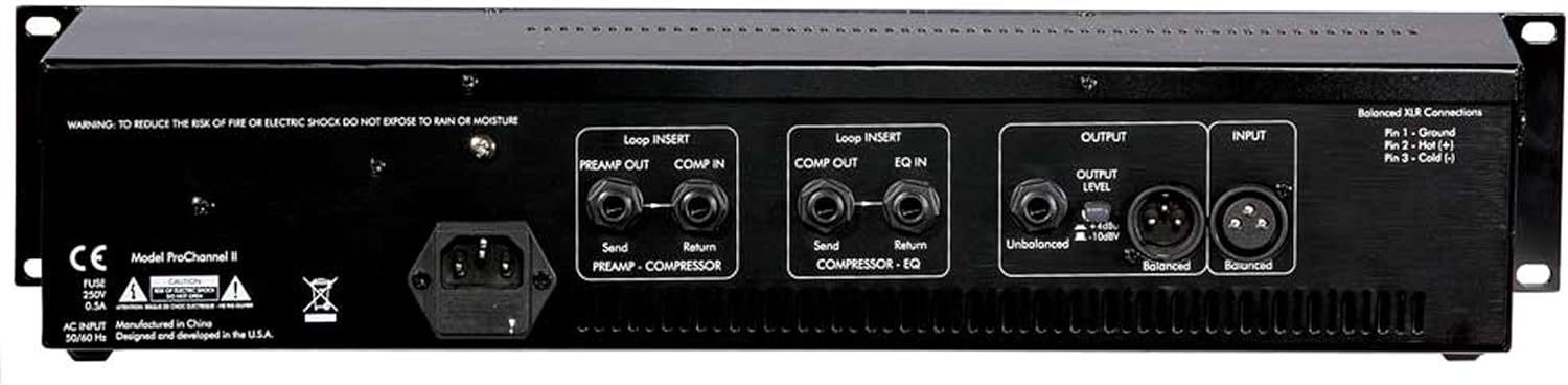
Figure 3.3.1: Rear Panel of the ART Pro Channel II. This view shows the AC power input, loop inserts for preamp/compressor and compressor/EQ, and balanced/unbalanced XLR and 1/4 inch TRS/TS input and output connections.
3.4 Connecting the Unit
- Power Connection: Connect the supplied AC power cord to the IEC inlet on the rear panel and then to a grounded AC outlet.
- Audio Input: Connect your microphone or line-level source to the XLR or 1/4 inch TRS/TS input on the rear panel. For microphones requiring phantom power, ensure it is enabled on the front panel.
- Audio Output: Connect the balanced XLR or unbalanced 1/4 inch TS output to your mixer, audio interface, or recording device.
- Loop Inserts: The unit features loop inserts for external processing. Use the 'PREAMP OUT / COMP IN' inserts to add effects between the preamp and compressor, and 'COMP OUT / EQ IN' inserts between the compressor and equalizer.
4. Operating Instructions
Allow the unit to warm up for approximately 15-30 minutes after powering on for optimal tube performance.
4.1 Microphone Preamp Section
- GAIN: Adjusts the input gain for the microphone or instrument input. Start with this control at its minimum setting.
- LOW-CUT: Engages a high-pass filter to remove unwanted low-frequency rumble.
- PHANTOM POWER: Provides +48V phantom power for condenser microphones. Activate only when using condenser microphones.
- IMPEDANCE: Selects the input impedance for the microphone input, allowing for optimal matching with various microphones.
4.2 Compressor Section
- THRESHOLD: Sets the level at which compression begins. Signals above this level will be compressed.
- RATIO: Determines the amount of compression applied once the threshold is exceeded. Higher ratios result in more aggressive compression.
- ATTACK: Controls how quickly the compressor reacts to signals exceeding the threshold.
- RELEASE: Controls how quickly the compressor returns to its uncompressed state after the signal falls below the threshold.
- OUTPUT: Adjusts the output level of the compressor section.
- OPTICAL/TUBE: Selects between the optical compressor circuit and the tube-based compressor circuit, offering different sonic characteristics.
4.3 Equalizer Section
- LOW: Controls the gain of the low-frequency band.
- LOW-MID: Controls the gain and frequency of the lower-midrange band. Features selectable Q for narrow or wide bandwidth.
- HIGH-MID: Controls the gain and frequency of the upper-midrange band. Features selectable Q for narrow or wide bandwidth.
- HIGH: Controls the gain of the high-frequency band.
4.4 Master Output and Metering
- MASTER OUTPUT: Controls the overall output level of the Pro Channel II.
- VU METER: Displays the signal level. The switch allows selection between monitoring the preamp output, compressor output, or main output.
5. Maintenance
5.1 Cleaning
Clean the unit with a soft, dry cloth. Do not use liquid cleaners or solvents, as they may damage the finish or internal components.
5.2 Tube Replacement
The Pro Channel II uses vacuum tubes which have a finite lifespan. If you notice a degradation in sound quality or increased noise, the tubes may need replacement. This procedure should ideally be performed by a qualified technician. Refer to the specifications for the correct tube types.
5.3 Environmental Considerations
Operate the unit in a well-ventilated area to prevent overheating. Avoid exposure to extreme temperatures, humidity, or direct sunlight. The unit contains sensitive electronic components and should be handled with care.
6. Troubleshooting
- No Sound:
- Check all cable connections (input, output, power).
- Ensure the unit is powered on and tubes are warmed up.
- Verify input and output gain settings are not at minimum.
- Confirm phantom power is engaged for condenser microphones.
- Hum or Noise:
- Ensure all audio cables are properly shielded and in good condition.
- Check for ground loops; try connecting all audio equipment to the same power strip.
- Move the unit away from power transformers, computer monitors, or other sources of electromagnetic interference.
- If hum persists, tubes may need replacement or professional inspection.
- Distorted Sound:
- Reduce input gain to prevent clipping.
- Check output levels to ensure they are not overdriving subsequent equipment.
- Verify that the compressor settings (Threshold, Ratio) are appropriate for the signal.
If you encounter persistent issues not resolved by these steps, contact ART customer support or a qualified service technician.
7. Specifications
| Feature | Specification |
|---|---|
| Brand | ART |
| Model Name | ProChannelII |
| Connectivity Technology | XLR, 1/4 inch TRS, 1/4 inch TS |
| Recommended Uses | Voice Recording, Video Recording, Streaming, Singing, Karaoke, Speech, Video Conference |
| Compatible Devices | Professional Audio Equipment |
| Number of Channels | 1 |
| Signal-to-Noise Ratio | 80 dB |
| Power Source | Corded Electric |
| Enclosure Material | Stainless Steel |
| Item Weight | 13.4 Pounds |
| Item Dimensions | 22.3 x 11.4 x 5.2 inches |
8. Warranty and Support
8.1 Warranty Information
The ART Pro Channel II comes with a 2-Year Warranty from the date of purchase. This warranty covers defects in materials and workmanship under normal use. Please retain your proof of purchase for warranty claims.
8.2 Customer Support
For technical assistance, service, or warranty inquiries, please contact ART customer support. Contact information can typically be found on the official ART website or in the product packaging.