Bosch 0928400529
Bosch Mass Air Flow Meter (MAF Sensor) HFM-6-CI
Instruction Manual
Model: 0928400529
1. Introduction
This instruction manual provides essential information for the proper understanding, installation, operation, and maintenance of your Bosch Mass Air Flow (MAF) Meter, model HFM-6-CI (Part Number 0928400529). Please read this manual thoroughly before handling or installing the product to ensure safe and effective use. This sensor is designed to accurately measure the amount of air entering the engine, which is crucial for optimal fuel efficiency and emissions control.
2. Safety Information
Always observe the following safety precautions when working with automotive components:
- Disconnect Battery: Before performing any work on the vehicle's electrical system, disconnect the negative terminal of the battery to prevent electrical shock or damage to components.
- Wear Protective Gear: Always wear appropriate personal protective equipment, such as safety glasses and gloves, when working on a vehicle.
- Engine Cool-Down: Ensure the engine is cool before working on any engine components to avoid burns.
- Professional Installation Recommended: Installation of this component may require specialized tools and knowledge. If you are not confident in your ability to perform the installation safely and correctly, it is highly recommended to seek assistance from a qualified automotive technician.
- Handle with Care: The MAF sensor contains delicate electronic components. Avoid dropping or subjecting the sensor to harsh impacts.
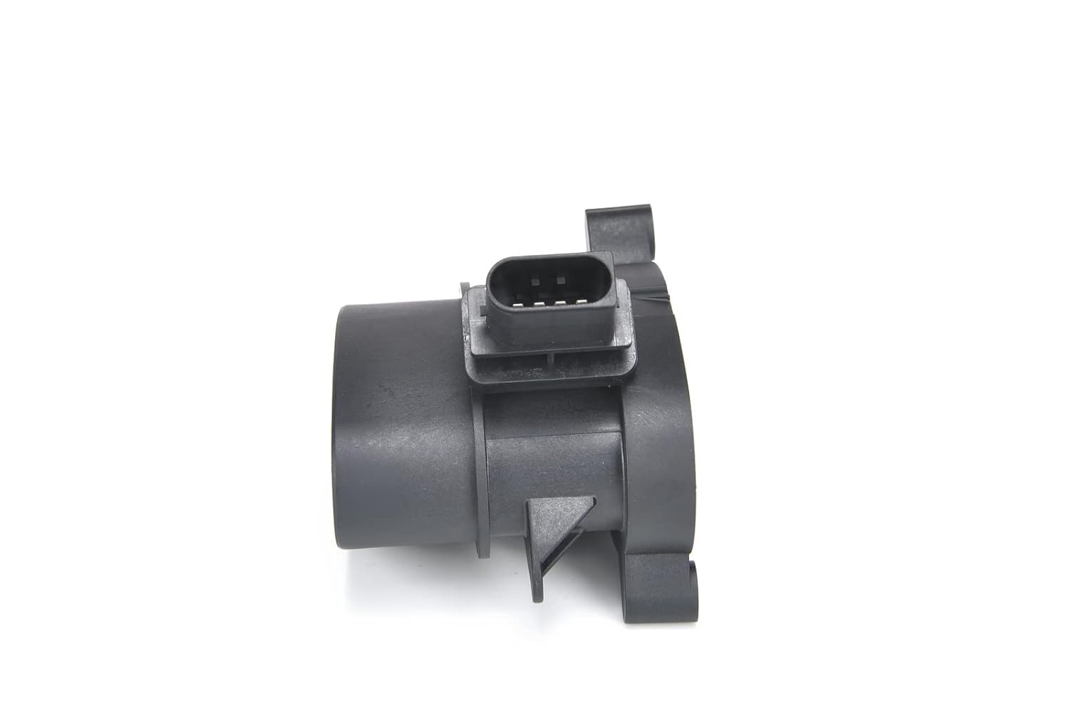
3. Product Overview
The Bosch Mass Air Flow (MAF) Meter is a critical component in modern engine management systems. It measures the mass of air flowing into the engine's intake manifold, providing essential data to the Engine Control Unit (ECU) for precise fuel injection and ignition timing. This ensures optimal engine performance, fuel economy, and reduced emissions.
Key Features:
- Robert Bosch GmbH Automotive Aftermarket quality.
- Part Number: 0928400529.
- Hot-Film Air-Mass Meter technology for accurate readings.


4. Setup and Installation
The Bosch Mass Air Flow Meter is designed for direct replacement in compatible vehicles. Proper installation is crucial for its correct function. Refer to your vehicle's specific service manual for detailed, model-specific instructions.
- Preparation: Ensure the engine is off and cool. Disconnect the negative terminal of the vehicle's battery. Locate the existing MAF sensor in the air intake system, typically between the air filter box and the throttle body.
- Removal of Old Sensor:
- Carefully disconnect the electrical connector from the old MAF sensor.
- Loosen any clamps or bolts securing the MAF sensor to the air intake ducting.
- Gently remove the old sensor from its housing. Be careful not to damage the intake ducting.
- Installation of New Sensor:
- Inspect the new Bosch MAF sensor for any visible damage.
- Insert the new sensor into the air intake ducting, ensuring it is seated correctly and the airflow direction arrow (if present) points towards the engine.
- Secure the sensor with the clamps or bolts previously removed. Do not overtighten.
- Reconnect the electrical connector to the new MAF sensor. Ensure it clicks into place securely.
- Post-Installation: Reconnect the negative terminal of the vehicle's battery. Start the engine and check for any warning lights. It may be necessary to clear any stored diagnostic trouble codes (DTCs) using an OBD-II scanner after installation, especially if the previous sensor was faulty.
Note: Some vehicles may require an ECU reset or a drive cycle to relearn air-fuel mixture parameters after MAF sensor replacement. Consult your vehicle's service manual or a qualified technician.
5. Operating Principles
The Bosch Hot-Film Mass Air Flow Meter operates by heating a thin platinum film or wire to a constant temperature above the ambient air temperature. As air flows past this heated element, it cools the film. The amount of electrical current required to maintain the constant temperature is directly proportional to the mass of air flowing through the sensor. This precise measurement is then converted into an electrical signal and sent to the vehicle's Engine Control Unit (ECU).
The ECU uses this air mass data, along with other sensor inputs (like oxygen sensor readings and engine speed), to calculate the optimal amount of fuel to inject into the cylinders and to determine the ignition timing. A properly functioning MAF sensor ensures efficient combustion, leading to:
- Improved fuel economy.
- Reduced exhaust emissions.
- Smooth engine idle and acceleration.
- Correct engine power output.
6. Maintenance
The Bosch MAF sensor is a precision instrument and generally requires minimal maintenance. However, its performance can be affected by contaminants in the air intake system. Consider the following:
- Air Filter Replacement: Regularly replace your vehicle's air filter according to the manufacturer's recommendations. A dirty or clogged air filter can allow contaminants to reach and foul the MAF sensor element.
- Avoid Oiled Air Filters: If using an aftermarket air filter, ensure it is not an "oiled" type, or if it is, ensure it is not over-oiled. Excess oil can contaminate the hot-film element of the MAF sensor, leading to inaccurate readings.
- Cleaning (Caution): While specialized MAF sensor cleaning sprays are available, cleaning should only be attempted if you are confident in the procedure and understand the risks. Improper cleaning can damage the delicate sensing element. Always follow the cleaner product's instructions carefully and avoid touching the sensing element.
- Inspection: Periodically inspect the MAF sensor and its wiring for any visible damage, loose connections, or signs of contamination.
7. Troubleshooting
A faulty Mass Air Flow sensor can lead to various engine performance issues. If you experience any of the following symptoms, your MAF sensor may require inspection or replacement:
- Check Engine Light (CEL): The most common indicator. Diagnostic Trouble Codes (DTCs) related to MAF sensor performance (e.g., P0100, P0101, P0102, P0103, P0104) will likely be stored.
- Rough Idle: Engine idles unevenly or stalls.
- Poor Acceleration: Engine feels sluggish or lacks power during acceleration.
- Reduced Fuel Economy: The engine may run too rich or too lean, leading to increased fuel consumption.
- Black Smoke from Exhaust: Indicates an overly rich fuel mixture.
- Engine Hesitation or Surging: Inconsistent power delivery.
Basic Diagnostic Steps:
- Check Connections: Ensure the electrical connector is securely attached to the MAF sensor and that there are no visible signs of damage to the wiring harness.
- Inspect Air Intake: Look for any leaks or cracks in the air intake hose or ducting between the MAF sensor and the throttle body. Unmetered air can cause incorrect readings.
- Air Filter Condition: Verify that the air filter is clean and properly installed.
- Scan for Codes: Use an OBD-II scanner to retrieve any stored diagnostic trouble codes. This can help pinpoint the issue.
If symptoms persist after basic checks, it is recommended to consult a qualified automotive technician for professional diagnosis and repair.
8. Specifications
| Attribute | Value |
|---|---|
| Brand | Bosch |
| Item Model Number | 0928400529 |
| Product Dimensions (L x W x H) | 15 x 12 x 11 cm |
| Item Weight | 0.27 Kilograms (270 g) |
| Mounting Type | Flange Mount |
| Output Type | Electrical Signal |
| Specific Uses for Product | Automotive |
| Global Trade Identification Number (GTIN) | 04047023450210 |
| Date First Available | 7 November 2019 |
| Is discontinued by manufacturer | No |
9. Warranty and Support
Bosch stands behind the quality of its automotive components. For specific warranty information regarding your Mass Air Flow Meter (Part Number 0928400529), please refer to the warranty documentation provided with your purchase or visit the official Bosch Automotive Aftermarket website. Warranty terms and conditions may vary by region and retailer.
For technical support, product inquiries, or assistance with installation, it is recommended to contact Bosch Automotive Aftermarket customer service or consult a certified Bosch service center. You can typically find contact information on the official Bosch website or through your product retailer.
Please retain your proof of purchase for warranty claims.
Related Documents - 0928400529
 |
Toyota Mass Air Flow (MAF) Meter Components - 2UZ-FE Engine Detailed diagram and identification of Mass Air Flow (MAF) Meter components for the Toyota 2UZ-FE engine, including the MAF meter and its connector. Service manual information. |
 |
AFH60M-27 Air Flow Meter Product Manual User manual for the AFH60M-27 air flow meter, covering product information, safety warnings, installation, operation, and maintenance. Includes compliance and manufacturer details. |
 |
Rheonik RHM 10 Coriolis Mass Flow Meter: Precision Batching, Filling, and Measurement Detailed datasheet for the Rheonik RHM 10 Coriolis Mass Flow Meter, designed for accurate batching, filling, and measurement applications. Features include high precision, wide operating ranges, robust construction, and various connection options for industrial use. |
 |
Fox Thermal Model FT1 Thermal Mass Flow Meter & Temperature Transmitter Instruction Manual Comprehensive instruction manual for the Fox Thermal Model FT1, detailing installation, operation, wiring, maintenance, and troubleshooting of this advanced thermal mass flow meter and temperature transmitter. |
 |
Air Flow Meter Installation Manual - JESBEN 22204-37010 Step-by-step installation guide for the JESBEN 22204-37010 Mass Air Flow (MAF) Meter, including tools, procedures, testing, and precautions for vehicle engine management systems. |
 |
2004 Toyota Prius DTC P0101 Repair Manual: Mass or Volume Air Flow Circuit Range/Performance Problem Technical repair manual instructions for diagnosing and resolving DTC P0101 (Mass or Volume Air Flow Circuit Range/Performance Problem) on a 2004 Toyota Prius. |
Ask a question about this manual
Ask about setup, troubleshooting, compatibility, parts, safety, or missing instructions. Manuals+ will review the question and use this page’s manual context to help answer it.