Sinometer UT60B
Uni-Trend UT60B Auto Ranging Multimeter User Manual
Model: UT60B | Brand: Sinometer
1. Introduction
This user manual provides comprehensive instructions for the safe and effective operation, maintenance, and troubleshooting of the Uni-Trend UT60B Auto Ranging Multimeter. The UT60B is a versatile digital multimeter designed for measuring AC/DC voltage, AC/DC current, resistance, capacitance, frequency, diode, and continuity. Please read this manual thoroughly before using the device to ensure proper functionality and safety.
2. Safety Information
Always adhere to the following safety precautions to prevent personal injury or damage to the multimeter or equipment under test.
- Do not exceed the maximum input limits for any function.
- Use extreme caution when working with voltages above 30V AC RMS, 42V peak, or 60V DC. These voltages pose a shock hazard.
- Before making resistance, continuity, or diode measurements, disconnect power to the circuit and discharge all high-voltage capacitors.
- Inspect the test leads for damaged insulation or exposed metal before use. Replace if damaged.
- Ensure the rotary switch is in the correct position for the desired measurement before connecting the test leads to the circuit.
- The UT60B is rated for CAT IV 600V and CAT III 1000V. Adhere to these safety categories when selecting measurement points.
- Do not operate the meter if it appears damaged or if the case is open.
- Replace the battery immediately when the low battery indicator appears to ensure accurate readings.
3. Product Overview
The Uni-Trend UT60B Multimeter features a clear LCD display, a central rotary switch for function selection, and various function buttons for enhanced measurement capabilities.
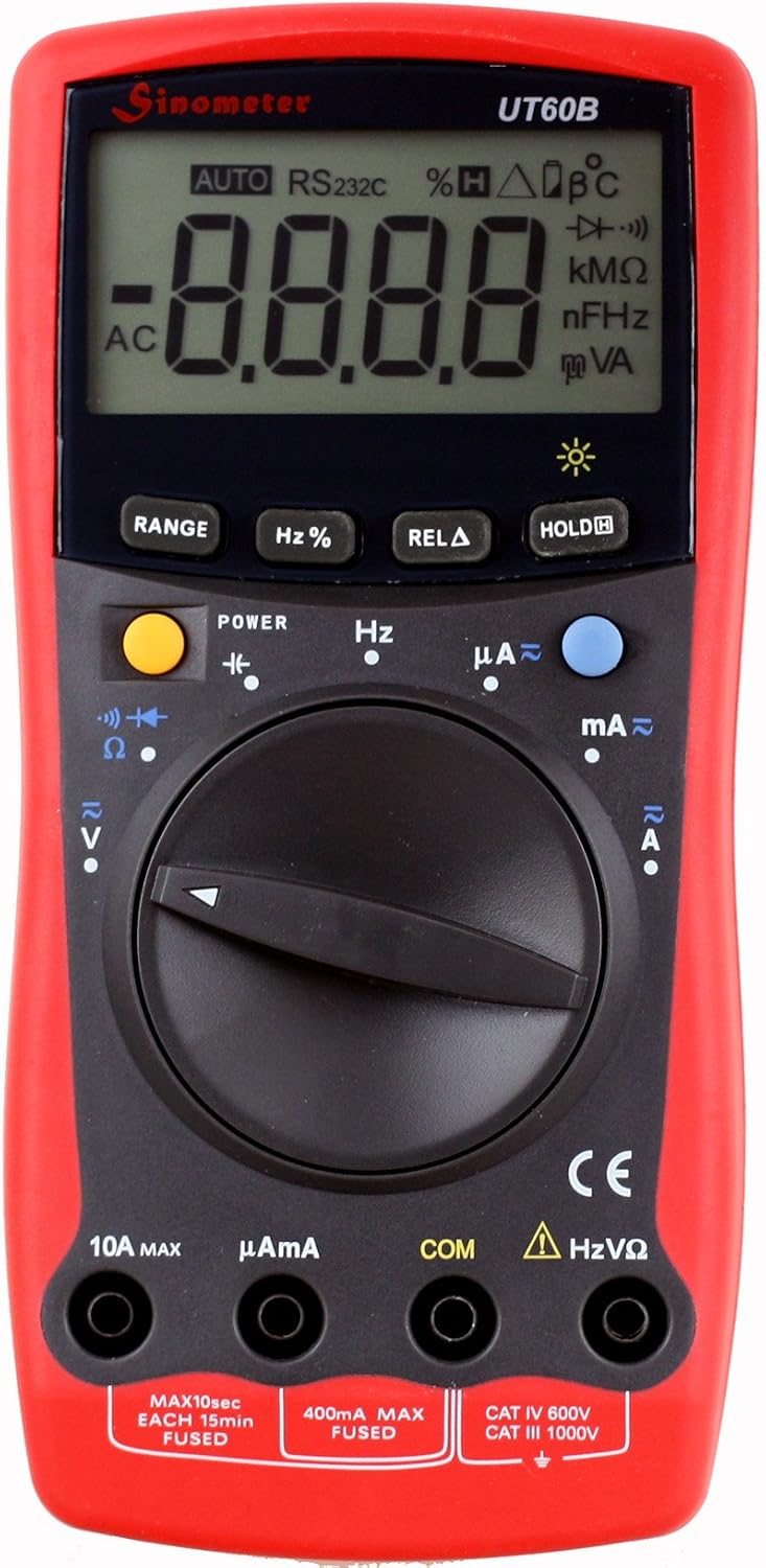
Figure 3.1: Front view of the UT60B Multimeter, highlighting the LCD display, rotary switch, and function buttons. The display shows "AUTO" and "AC" indicating auto-ranging and AC measurement mode.

Figure 3.2: The UT60B Multimeter accompanied by its standard accessories, including red and black test leads and the instruction manual, ready for use.

Figure 3.3: Side-angled view of the UT60B Multimeter, demonstrating its integrated kickstand for convenient hands-free operation on a workbench.
3.1. Components
- LCD Display: Shows measurement readings, units, and function indicators.
- Rotary Switch: Used to select the desired measurement function (e.g., V~, V=, A~, A=, Ohm, Capacitance, Frequency, Diode/Continuity).
- Function Buttons:
- POWER: Turns the multimeter on or off.
- RANGE: Manually selects the measurement range (disables auto-ranging).
- Hz%: Toggles between frequency and duty cycle measurement.
- RELA (Relative Mode): Stores the current reading as a reference value, displaying subsequent measurements as a deviation from this reference.
- HOLD: Freezes the current reading on the display.
- Input Jacks:
- COM: Common input jack for all measurements (connect black test lead).
- VΩHz: Input jack for voltage, resistance, frequency, capacitance, diode, and continuity measurements (connect red test lead).
- µAmA: Input jack for microampere and milliampere current measurements (connect red test lead).
- 10A MAX: Input jack for high current (up to 10A) measurements (connect red test lead).
4. Setup
4.1. Battery Installation
The UT60B Multimeter requires batteries for operation. Batteries are not included with the product.
- Ensure the multimeter is turned off.
- Locate the battery compartment cover on the back of the unit.
- Use a screwdriver to remove the screw securing the battery cover.
- Carefully remove the cover.
- Insert the required batteries, observing the correct polarity (+ and -) as indicated inside the compartment.
- Replace the battery cover and secure it with the screw.
4.2. Connecting Test Leads
Always connect the black test lead to the COM (Common) input jack. Connect the red test lead to the appropriate input jack based on the measurement you intend to perform:
- For Voltage, Resistance, Capacitance, Frequency, Diode, and Continuity measurements: Connect the red test lead to the VΩHz jack.
- For Microampere (µA) or Milliampere (mA) current measurements: Connect the red test lead to the µAmA jack.
- For Ampere (A) current measurements (up to 10A): Connect the red test lead to the 10A MAX jack.
5. Operating Instructions
5.1. Power On/Off
Press the POWER button to turn the multimeter on. Press and hold the POWER button again to turn it off.
5.2. Auto Ranging
The UT60B features auto-ranging, which automatically selects the appropriate measurement range for the input signal. This is indicated by "AUTO" on the display. For manual range selection, press the RANGE button. Each press will cycle through available ranges. To return to auto-ranging, press and hold the RANGE button.
5.3. Data Hold
Press the HOLD button to freeze the current reading on the display. Press HOLD again to release the data hold function.
5.4. Relative Mode (RELA)
Relative mode allows you to set a reference value and display subsequent measurements as a deviation from that reference. Press the RELA button to activate. The current reading will be stored as the reference, and the display will show "RELA" and the difference from the reference. Press RELA again to exit this mode.
6. Measurement Functions
Turn the rotary switch to the desired function. Ensure test leads are connected to the correct input jacks.
6.1. DC Voltage Measurement (V=)
- Set the rotary switch to the V= position.
- Connect the black test lead to the COM jack and the red test lead to the VΩHz jack.
- Connect the test leads across the component or circuit to be measured, observing polarity.
- Read the voltage value on the LCD.
6.2. AC Voltage Measurement (V~)
- Set the rotary switch to the V~ position.
- Connect the black test lead to the COM jack and the red test lead to the VΩHz jack.
- Connect the test leads across the AC voltage source.
- Read the voltage value on the LCD.
6.3. DC/AC Current Measurement (A=, A~, mA=, mA~, µA=, µA~)
CAUTION: Never connect the multimeter in parallel to a voltage source when measuring current. Always connect in series with the load.
- Determine if the current is AC or DC and estimate the magnitude.
- For µA or mA, set the rotary switch to µAmA and connect the red lead to the µAmA jack.
- For A (up to 10A), set the rotary switch to A and connect the red lead to the 10A MAX jack.
- Break the circuit and connect the multimeter in series with the load.
- Read the current value on the LCD.
6.4. Resistance Measurement (Ω)
CAUTION: Ensure the circuit is de-energized and all capacitors are discharged before measuring resistance.
- Set the rotary switch to the Ω position.
- Connect the black test lead to COM and the red test lead to VΩHz.
- Connect the test leads across the resistor or component.
- Read the resistance value on the LCD.
6.5. Capacitance Measurement (nF, µF)
CAUTION: Ensure the capacitor is fully discharged before measurement to prevent damage to the meter.
- Set the rotary switch to the Capacitance position (indicated by a capacitor symbol).
- Connect the black test lead to COM and the red test lead to VΩHz.
- Connect the test leads across the capacitor.
- Read the capacitance value on the LCD.
6.6. Frequency Measurement (Hz)
- Set the rotary switch to the Hz position.
- Connect the black test lead to COM and the red test lead to VΩHz.
- Connect the test leads across the signal source.
- Read the frequency value on the LCD. Press Hz% to toggle to duty cycle measurement if needed.
6.7. Diode Test (→|→)
- Set the rotary switch to the Diode/Continuity position.
- Connect the black test lead to COM and the red test lead to VΩHz.
- Connect the red test lead to the anode and the black test lead to the cathode of the diode.
- A good silicon diode will typically show a forward voltage drop between 0.5V and 0.8V. Reverse polarity should show "OL" (Over Load).
6.8. Continuity Test (♫)
- Set the rotary switch to the Diode/Continuity position.
- Connect the black test lead to COM and the red test lead to VΩHz.
- Connect the test leads across the circuit or component.
- If the resistance is below a certain threshold (typically <50Ω), the buzzer will sound, indicating continuity. The display will show the resistance value.
7. Maintenance
7.1. Cleaning
Wipe the case with a damp cloth and mild detergent. Do not use abrasives or solvents. Ensure the meter is off and disconnected from any circuits before cleaning.
7.2. Battery Replacement
When the low battery indicator appears on the display, replace the batteries immediately to ensure accurate measurements. Refer to Section 4.1 for battery installation instructions.
7.3. Fuse Replacement
The UT60B Multimeter is protected by fuses. If the current measurement function fails, the fuse may need replacement. Always replace with a fuse of the specified type and rating.
- 400mA MAX FUSED: For µA and mA ranges.
- 10A MAX FUSED: For 10A range.
To replace fuses, follow the battery replacement procedure to open the back case. The fuses are typically located near the input jacks. Carefully remove the old fuse and insert the new one.
8. Troubleshooting
| Problem | Possible Cause | Solution |
|---|---|---|
| No display or dim display | Low or dead batteries. | Replace batteries (refer to Section 4.1). |
| "OL" (Over Load) displayed | Input value exceeds selected range; open circuit in resistance/continuity. | Switch to a higher range (if not auto-ranging); check circuit for breaks. |
| Incorrect current readings | Blown fuse; incorrect input jack connection. | Check and replace fuse (refer to Section 7.3); ensure red lead is in correct current jack (µAmA or 10A MAX). |
| No continuity beep | Circuit resistance is too high; open circuit. | Check the circuit for breaks or high resistance. |
9. Specifications
| Parameter | Value |
|---|---|
| Max. LCD Display | 3,999 counts |
| Range Selection | Auto-ranging |
| DC Voltage (V=) | 400mV, 4V, 40V, 400V (±0.8%); 1000V (±1.0%) |
| AC Voltage (V~) | 4V, 40V, 400V (±1.0%); 750V (±1.2%) |
| DC Current (A=) | Up to 10A |
| AC Current (A~) | Up to 10A |
| Resistance (Ω) | Ranges not fully specified, but included. |
| Capacitance | Ranges not fully specified, but included. |
| Frequency | Ranges not fully specified, but included. |
| Diode Test | Yes |
| Continuity Test | Yes (with buzzer) |
| Power Source | Battery Powered (Batteries not included) |
| Item Weight | 10.56 ounces (approx. 299g) |
| Product Dimensions (L x W x H) | 6.75 x 1.5 x 3.25 inches (approx. 17.1 x 3.8 x 8.3 cm) |
| Safety Rating | CAT IV 600V, CAT III 1000V |
| Manufacturer | Sinometer (OEM by Uni-Trend) |
| Model Number | UT60B |
10. Warranty and Support
For warranty information and technical support, please refer to the documentation provided with your purchase or contact the seller or manufacturer directly. Specific warranty terms may vary by region and retailer.
Ask a question about this manual
Ask about setup, troubleshooting, compatibility, parts, safety, or missing instructions. Manuals+ will review the question and use this page’s manual context to help answer it.