1. Introduction
This manual provides essential instructions for the safe and effective use of the Potter & Brumfield K10P-11D15-110V Relay. It covers product overview, detailed specifications, proper installation procedures, operational guidelines, routine maintenance, and troubleshooting tips to ensure optimal performance and longevity of the device. Please read this manual thoroughly before installation and operation.
2. Product Overview
The K10P-11D15-110V is a general-purpose DPDT (Double Pole Double Throw) power relay manufactured by Potter & Brumfield, a brand of TE Connectivity. It is designed for industrial electrical applications, featuring a 110VDC coil voltage and a 15A current rating. The relay utilizes a plug-in mounting type and has 8 blades for electrical connection. This robust component is suitable for various control and switching tasks in industrial environments.

Figure 1: The Potter & Brumfield K10P-11D15-110V Relay shown in its protective packaging.

Figure 2: Detailed view of the product label, indicating model number K10P-11D15-110 and specifications.
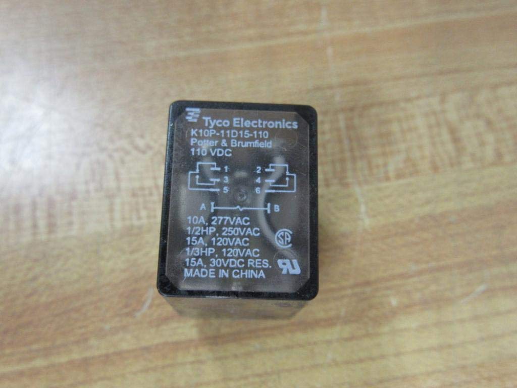
Figure 3: Top surface of the relay, displaying the internal pinout diagram and key electrical ratings for safe operation.

Figure 4: The underside of the relay, clearly showing the 8 plug-in pins for socket mounting.

Figure 5: Side profile of the relay, illustrating its compact form factor.
3. Specifications
| Feature | Specification |
|---|---|
| Model Number | K10P-11D15-110V |
| Brand | Potter & Brumfield (Tyco Electronics) |
| Coil Voltage (Nominal) | 110 VDC |
| Coil Resistance | 11000 ohm |
| Number of Poles | 2 |
| Contact Configuration | DPDT (Double Pole Double Throw), Normally Open |
| Relay Mounting | Plug In Mount |
| Carry Current (Max) | 15 Amps |
| Contact Material | Silver |
| Connector Type | Plug-In |
| Product Dimensions | 8 x 8 x 8 inches |
| Product Weight | 1.3 Pounds |
4. Setup and Installation
Proper installation is crucial for the safe and reliable operation of the relay. Follow these steps carefully:
- Safety First: Always ensure that all power to the circuit where the relay will be installed is completely disconnected and locked out before beginning any installation work.
- Identify Compatible Socket: Use an appropriate 8-pin relay socket that is specifically designed and compatible with the K10P-11D15-110V relay.
- Align Pins: Carefully align the 8 blades (pins) of the relay with the corresponding slots in the relay socket. Refer to the pinout diagram on the relay (Figure 3) or the socket's documentation for correct orientation.
- Insert Relay: Gently push the relay into the socket until it is fully seated. Ensure all pins are securely engaged. Do not force the relay, as this can bend or damage the pins.
- Wiring Connections:
- Connect the control circuit (110VDC) to the coil terminals of the socket. Typically, for an 8-pin relay, these are pins 2 and 7, but always verify with the specific socket diagram or relay datasheet.
- Connect the load circuit(s) to the contact terminals (common, normally open, normally closed) as required by your application.
- Verify Connections: Double-check all wiring for correct polarity, secure connections, and proper insulation.
- Restore Power: Once installation is complete and thoroughly verified, restore power to the circuit.
5. Operation
The K10P-11D15-110V is a DPDT (Double Pole Double Throw) relay, meaning it has two independent sets of contacts, each capable of switching between two positions. Its operation is straightforward:
- De-energized State: When no voltage is applied to the coil terminals, the relay's contacts are in their default, or 'normally open' (NO) and 'normally closed' (NC) positions. The NO contacts are open, and the NC contacts are closed.
- Energized State: When the specified 110VDC is applied to the coil terminals, an electromagnetic field is generated. This field attracts an armature, causing the two sets of contacts to switch their state. The NO contacts will close, and the NC contacts will open, allowing current to flow through the connected load circuits as intended.
- Current Rating: The contacts are rated for a maximum of 15 Amps. It is critical not to exceed this current rating to prevent damage to the relay, connected equipment, and potential safety hazards.
6. Maintenance
The K10P-11D15-110V relay is designed for durability, but regular inspection and proper care can extend its lifespan and ensure reliable performance:
- Regular Inspection: Periodically inspect the relay and its socket for any visible signs of wear, corrosion, discoloration (indicating overheating), or physical damage.
- Cleanliness: Keep the relay and its surrounding environment free from excessive dust, dirt, moisture, and corrosive substances. A clean, dry environment is essential for optimal operation.
- Contact Integrity: Although this is a sealed unit, ensure that the connections between the relay pins and the socket terminals remain firm and secure. Loose connections can lead to increased resistance, localized heating, and intermittent operation.
- Replacement: If the relay exhibits signs of malfunction, such as inconsistent switching, excessive heat generation, or visible damage, it should be replaced immediately with an identical model to maintain system integrity and safety.
7. Troubleshooting
If you encounter issues with your K10P-11D15-110V relay, consider the following troubleshooting steps:
- Relay Not Switching:
- Verify that the correct 110VDC coil voltage is being supplied to the coil terminals. Use a multimeter to confirm voltage presence.
- Check for loose, corroded, or damaged connections at the coil terminals and within the socket.
- Ensure the relay is properly and fully seated in its socket.
- Load Not Activating (or Activating Incorrectly):
- Confirm that the relay coil is energizing. A faint audible 'click' should be heard when the coil is powered. You can also use a multimeter to check for continuity across the appropriate contacts when the coil is energized.
- Check the wiring to the load for continuity, correct connections (e.g., ensuring the load is connected to the Normally Open contacts if it should activate when the relay is energized), and any breaks in the circuit.
- Ensure the load itself is functional and not faulty.
- Verify that the current drawn by the load does not exceed the relay's 15A contact rating. Overcurrent can damage contacts or prevent proper switching.
- Overheating:
- Excessive current flowing through the contacts or the coil can cause the relay to overheat. Double-check that the load current is within the specified 15A limit.
- Ensure there is adequate ventilation around the relay to dissipate heat.
- Loose or high-resistance connections can also cause localized heating at the terminals.
8. Warranty and Support
Warranty information for the Potter & Brumfield K10P-11D15-110V Relay is typically provided by the manufacturer or the point of purchase. Please refer to your original purchase documentation or contact the seller for specific warranty terms and conditions.
For technical support, detailed datasheets, or further inquiries, it is recommended to contact Potter & Brumfield directly or visit the official TE Connectivity website, as Potter & Brumfield is a brand under TE Connectivity. Your distributor may also be able to provide support.
- Manufacturer: Potter & Brumfield (a brand of TE Connectivity)
- Official Website: TE Connectivity (for Potter & Brumfield product information)