1. Introduction and Overview
The MFJ-874 is a precision RF Power and SWR meter designed for amateur radio applications across a wide frequency range. It provides accurate measurements for both forward and reflected power, as well as Standing Wave Ratio (SWR), for HF, VHF, and UHF bands.
This meter features a large, illuminated display for easy readability, selectable power ranges, and an expanded SWR scale for precise adjustments. It is housed in a durable metal cabinet, ensuring longevity and reliable performance.
Key Features:
- Frequency Coverage: 1.8 MHz to 525 MHz
- Power Ranges: 5 Watts, 20 Watts, 200 Watts
- Large, Illuminated Meter: 3.25 x 1.25 inches for clear viewing
- SWR Scale: Expanded for precise 3:1 SWR readings at mid-scale
- Measurement Modes: Peak and Average power, Forward and Reflected power
- Connectors: Air dielectric SO-239 with gold-plated center pins

Figure 1.1: Front view of the MFJ-874 RF Power & SWR Meter, showing the large analog display, function and range selectors, and frequency band switch. The packaging highlights its 'GrandMaster' series designation.
2. Setup
Proper setup is crucial for accurate measurements and safe operation of your MFJ-874 meter. Follow these steps carefully:
2.1 Unpacking and Inspection
- Carefully remove the MFJ-874 meter from its packaging.
- Inspect the unit for any signs of physical damage that may have occurred during shipping.
- Verify that all included components are present, specifically the power pigtail for the meter lamp.
2.2 Connecting the Meter
The MFJ-874 uses standard SO-239 connectors for RF input and output. Ensure all connections are secure to prevent signal loss and potential damage.
- Transmitter Connection: Connect the RF output from your transmitter or amplifier to the SO-239 connector labeled TRANSMITTER on the rear panel of the MFJ-874. Use a high-quality coaxial cable.
- Antenna Connection: Connect your antenna system (antenna, tuner, dummy load, etc.) to the SO-239 connector labeled ANTENNA on the rear panel of the MFJ-874. Use a high-quality coaxial cable.
- Meter Lamp Power: The meter lamp requires 13.8 VDC or 110 VAC for illumination. Connect the provided power pigtail to the 12V DC input on the rear panel. Connect the other end of the pigtail to a suitable 13.8 VDC power supply or 110 VAC source, depending on your setup. The meter will function without the lamp powered, but illumination aids readability in low-light conditions.
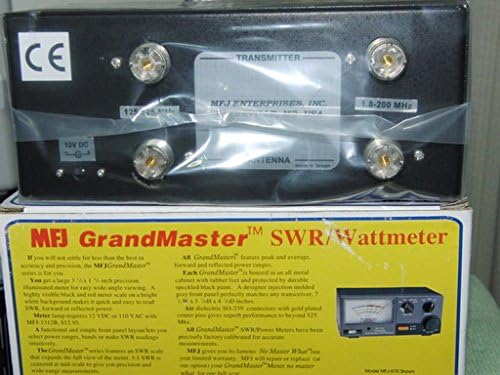
Figure 2.1: Rear panel of the MFJ-874, illustrating the SO-239 connectors for Transmitter and Antenna, along with the 12V DC input for the meter lamp. Note the frequency markings for the connectors.
2.3 Placement
Place the MFJ-874 meter on a stable, level surface near your radio equipment. Ensure adequate ventilation and avoid placing it near strong magnetic fields or sources of excessive heat.
3. Operating Instructions
This section details the steps for using your MFJ-874 meter to measure RF power and SWR.
3.1 Powering the Meter Lamp
If you have connected the 13.8 VDC or 110 VAC power source to the meter lamp input, the lamp will illuminate when power is applied. This enhances visibility of the meter face.
3.2 Selecting Frequency Band
Locate the VHF/UHF HF switch on the front panel. Set this switch according to the frequency band you are operating on:
- HF: For frequencies from 1.8 MHz to 30 MHz.
- VHF/UHF: For frequencies from 50 MHz to 525 MHz.
3.3 Selecting Power Range
The RANGE knob on the front panel allows you to select the maximum power range for your measurements. Choose the range that best suits your transmitter's output power:
- 5W: For low power operations (e.g., QRP).
- 20W: For medium power operations.
- 200W: For high power operations.
Always start with a higher power range and decrease it if the reading is too low, to avoid pegging the meter needle.
3.4 Measuring Forward and Reflected Power
The FUNCTION switch allows you to select between Forward (FWD) and Reflected (REF) power readings.
- Set the FUNCTION switch to FWD.
- Transmit a steady carrier (e.g., using CW or FM mode) at your desired power level.
- Read the forward power directly from the meter scale corresponding to your selected power range.
- Set the FUNCTION switch to REF.
- Transmit again. Read the reflected power from the meter scale.
3.5 Measuring SWR (Standing Wave Ratio)
The MFJ-874 provides an accurate method for measuring SWR, which is critical for antenna tuning.
- Set the FUNCTION switch to FWD.
- Select an appropriate RANGE (e.g., 20W or 200W) to get a good deflection on the meter.
- Transmit a steady carrier.
- Adjust the CAL knob (located on the front panel) until the meter needle points exactly to the CAL mark on the meter scale. This calibrates the meter for the current forward power.
- Without changing the transmitter power or the CAL knob setting, switch the FUNCTION switch to SWR.
- Read the SWR directly from the SWR scale on the meter. The SWR scale is designed to be expanded, with 3:1 SWR centered at mid-scale for enhanced precision.
- After measurement, release the transmit key.
3.6 Peak and Average Power Readings
The MFJ-874 supports both peak and average power readings. Use the PEP AVG switch on the front panel to select the desired mode:
- AVG: Displays the average power of the transmitted signal.
- PEP: Displays the Peak Envelope Power, useful for SSB and other modulated modes.
4. Maintenance
The MFJ-874 is designed for reliable operation with minimal maintenance. Following these guidelines will help ensure its longevity.
4.1 Cleaning
To clean the exterior of the meter, use a soft, dry cloth. For stubborn dirt, a slightly damp cloth with a mild, non-abrasive cleaner can be used. Ensure no liquid enters the unit. Do not use harsh chemicals or solvents, as these can damage the finish or internal components.
4.2 Storage
When not in use for extended periods, store the MFJ-874 in a dry, dust-free environment. Disconnect all cables and, if possible, store it in its original packaging or a protective case to prevent physical damage.
4.3 Calibration
The MFJ-874 meters are precisely factory calibrated for accurate measurements. Routine user calibration is not typically required. If you suspect a calibration issue, it is recommended to contact MFJ customer support or a qualified service technician.
5. Troubleshooting
If you encounter issues with your MFJ-874 meter, review the following common problems and solutions before seeking professional assistance.
5.1 No Meter Lamp Illumination
- Check Power Connection: Ensure the 13.8 VDC or 110 VAC power pigtail is securely connected to both the meter and the power source.
- Verify Power Source: Confirm that the power source is active and providing the correct voltage.
- Inspect Pigtail: Check the power pigtail for any damage or loose connections.
5.2 No Meter Deflection or Incorrect Readings
- Check RF Connections: Ensure all coaxial cables are securely connected to the TRANSMITTER and ANTENNA ports. Loose connections can cause inaccurate readings or no signal pass-through.
- Verify Transmitter Output: Confirm that your transmitter is actually outputting RF power.
- Select Correct Power Range: Ensure the RANGE knob is set to an appropriate power level for your transmitter. If the range is too high, the needle deflection may be minimal. If too low, the meter may peg.
- Select Correct Frequency Band: Ensure the VHF/UHF HF switch is set to the correct band for your operating frequency.
- SWR Calibration: If measuring SWR, ensure you have properly calibrated the meter using the CAL knob while in FWD mode before switching to SWR mode.
- Function Switch Position: Verify the FUNCTION switch is set to FWD, REF, or SWR as intended for your measurement.
5.3 Erratic or Unstable Readings
- Check Coaxial Cables: Inspect all coaxial cables for damage, kinks, or faulty connectors. Replace any suspect cables.
- Antenna System Issues: Problems with your antenna, antenna tuner, or feedline can cause unstable SWR readings. Verify the integrity of your entire antenna system.
- RF Interference: Strong local RF interference can sometimes affect meter readings. Try operating in a different environment if possible.
6. Specifications
| Feature | Specification |
|---|---|
| Model Number | MFJ-874 |
| Frequency Range | 1.8 - 525 MHz (HF/VHF/UHF) |
| Power Ranges | 5W, 20W, 200W |
| Meter Type | Analog, Illuminated |
| Meter Size | 3.25 x 1.25 inches |
| Connectors | SO-239 (UHF type), gold-plated center pins |
| Meter Lamp Power | 13.8 VDC or 110 VAC (via included pigtail) |
| Housing | All metal cabinet with rubber feet |
| Weight | 1.65 Pounds (approximately) |
| Included Components | 1 x Power Supply (pigtail for meter lamp) |
7. Warranty Information
The MFJ-874 RF Power & SWR Meter comes with a 30-day warranty from the date of purchase. This warranty covers defects in materials and workmanship under normal use. Please retain your proof of purchase for warranty claims.
For specific warranty terms and conditions, or to initiate a warranty claim, please refer to the official MFJ website or contact their customer service department.
8. Support
Should you require technical assistance, have questions about the operation of your MFJ-874 meter, or need to report a problem, please contact MFJ customer support.
- Online Resources: Visit the official MFJ website for product documentation, FAQs, and support contact information.
- Dealer Support: Your authorized MFJ dealer may also be able to provide assistance and support.
When contacting support, please have your product model (MFJ-874) and a detailed description of the issue ready to facilitate a quicker resolution.