GRI 4700A
GRI 4700-A Series Industrial Track Mount Switch User Manual
Model: 4700A
Introduction
The GRI 4700-A Series Industrial Track Mount Switch is a robust, wide-gap closed-loop magnetic contact designed for reliable monitoring in industrial environments. It is typically used in security systems, access control, or process automation to detect the open or closed state of doors, gates, or other movable barriers. Its durable construction ensures long-term performance in demanding conditions.
Product Overview
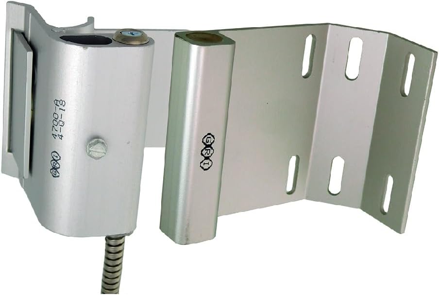
The image displays the GRI 4700-A Series Industrial Track Mount Switch. It consists of two primary components: the main switch unit (left) and the magnetic actuator (right), which is integrated into an L-shaped mounting bracket. The main switch unit features a durable housing, a flexible metallic conduit for wiring protection, and visible markings including "GRI" and "4700-A". The L-shaped bracket is designed for track mounting and has multiple elongated slots for flexible installation. This design allows for wide gap applications, ensuring reliable detection even with slight misalignments.
Setup and Installation
Proper installation is crucial for the reliable operation of the 4700-A Series switch. Follow these steps carefully:
- Mounting Location: Select a mounting location on the door, gate, or movable barrier and its frame where the switch and magnet can be aligned parallel to each other when the barrier is closed. Ensure the surfaces are clean and stable.
- Mounting the Switch Unit: Secure the main switch unit to the stationary frame using appropriate screws or bolts through its mounting holes. Ensure it is firmly attached and does not wobble.
- Mounting the Magnet Unit: Attach the L-shaped magnetic actuator bracket to the movable part of the barrier (door/gate). Align it precisely with the switch unit so that the magnet is directly opposite the switch when the barrier is closed. The elongated slots on the bracket allow for fine adjustment to achieve optimal alignment and gap.
- Wiring: The 4700-A Series is a closed-loop switch. Connect the two wires from the flexible conduit to your control panel or alarm system's closed-loop circuit. Ensure all connections are secure and insulated. Refer to your control panel's manual for specific wiring diagrams.
- Testing: After installation and wiring, test the switch by opening and closing the barrier. Verify that the circuit changes state as expected (e.g., alarm triggers when opened, disarms when closed). Adjust the magnet's position if necessary to ensure consistent operation.
Note: Always disconnect power to the control panel before performing any wiring to prevent electrical shock or damage to equipment.
Operating Principles
The GRI 4700-A Series switch operates on the principle of magnetic proximity. It consists of a reed switch encapsulated within the main unit and a permanent magnet within the L-shaped bracket. When the magnet is in close proximity to the reed switch (i.e., the door/gate is closed), the reed switch contacts are held closed, completing the electrical circuit. When the magnet moves away from the switch (i.e., the door/gate is opened), the reed switch contacts open, breaking the circuit. This change in circuit state is detected by the connected control panel, signaling an open condition.
- Closed State: Magnet is aligned with the switch; circuit is closed.
- Open State: Magnet is moved away from the switch; circuit is open.
Maintenance
The GRI 4700-A Series switch is designed for minimal maintenance due to its robust construction. However, periodic inspection can help ensure continued reliable operation:
- Cleaning: Periodically wipe down the exterior of the switch and magnet units with a clean, damp cloth to remove dust, dirt, or debris. Avoid using abrasive cleaners or solvents.
- Alignment Check: Regularly inspect the alignment of the switch and magnet. Ensure they remain parallel and within the specified operating gap when the barrier is closed. Adjust if necessary.
- Cable Inspection: Check the flexible metallic conduit and wiring for any signs of damage, fraying, or corrosion. Repair or replace damaged wiring immediately.
- Mounting Security: Verify that all mounting screws or bolts are tight and that the units are securely fastened to their respective surfaces.
Troubleshooting
If you experience issues with your GRI 4700-A Series switch, consider the following troubleshooting steps:
- Switch Not Activating/Deactivating:
- Misalignment: Check if the magnet and switch are perfectly aligned when the barrier is closed. Adjust their positions to ensure optimal proximity.
- Excessive Gap: Ensure the gap between the switch and magnet is within the specified operating range. The 4700-A is a wide-gap switch, but extreme distances will prevent activation.
- Wiring Issues: Inspect all wiring connections for looseness, corrosion, or breaks. Test continuity of the wires if possible.
- Damaged Unit: If the unit has sustained physical damage, it may need replacement.
- Intermittent Operation:
- Loose Mounting: Ensure both the switch and magnet are securely mounted and do not shift during barrier movement.
- Vibrations: Excessive vibrations in the environment might cause intermittent contact. Ensure stable mounting.
- Environmental Factors: Extreme temperatures or moisture, though the unit is industrial-grade, can sometimes affect performance.
- False Alarms:
- External Magnetic Fields: Ensure there are no strong external magnetic fields near the switch that could interfere with its operation.
- Physical Obstructions: Check for any physical obstructions that might prevent the barrier from fully closing, leaving the switch in an open state.
If problems persist after attempting these steps, contact a qualified technician or the manufacturer for further assistance.
Specifications
| Feature | Detail |
|---|---|
| Model Number | 4700A |
| Description | Industrial Wide Gap Track Mount Closed Loop Switch |
| Manufacturer | G.R.I. |
| Product Dimensions | 8 x 4 x 11 inches |
| First Available Date | December 28, 2010 |
| Circuit Type | Closed Loop |
| Mounting Type | Track Mount |
Warranty and Support
For detailed information regarding the warranty terms and conditions for your GRI 4700-A Series Industrial Track Mount Switch, please refer to the documentation provided with your purchase or visit the official G.R.I. (George Risk Industries) website. Warranty coverage typically addresses manufacturing defects under normal use.
For technical support, troubleshooting assistance beyond this manual, or to inquire about replacement parts, please contact G.R.I. customer service directly. Contact information can usually be found on the manufacturer's website or product packaging.
Ask a question about this manual
Ask about setup, troubleshooting, compatibility, parts, safety, or missing instructions. Manuals+ will review the question and use this page’s manual context to help answer it.